
Stress function calibration method

a function and stress technology, applied in the field of stress function calibration, can solve the problems of expensive and time-consuming inspection and reworking, shorten the fatigue life of the workpiece, and distortion is another undesirable

Active Publication Date: 2014-02-04
THE BOEING CO
View PDF4 Cites 21 Cited by
  • Summary
  • Abstract
  • Description
  • Claims
  • Application Information

AI Technical Summary

Benefits of technology

The present patent discloses a method and system for predicting distortion in a workpiece caused by a selected manufacturing operation. The method involves calculating a moment coefficient of residual stress induced in a plate coupon, calibrating a stress function to this coefficient, and applying the calibrated stress function to a model of the workpiece to predict the distortion and residual stress in the workpiece. The technical effects of this invention include improved accuracy in predicting workpiece distortion and residual stress, which can aid in the development and improvement of manufacturing processes.

Problems solved by technology

Residual stress that is predominantly tensile is generally detrimental to fatigue strength and may shorten the fatigue life of the workpiece.
Distortion is another undesirable effect of residual stress that may occur in a workpiece following a manufacturing operation.
Unfortunately, moderate distortion may result in expensive and time-consuming inspection and reworking to bring the workpiece within design tolerances.
Excessive distortion may lead to scrapping of the workpiece and fabrication of a replacement.
For example, during high-speed machining, a cutting tool may be rotated at relatively high speed and / or the cutting tool may be driven into the workpiece at a relatively high feed rate which, depending on the machining parameters, may result in non-optimal machining of the workpiece.
Non-optimal machining is believed to increase residual stress and distortion in a workpiece as compared to more conventional machining.
Unfortunately, current systems and methods of estimating residual stress are generally inadequate.
Furthermore, current methods of verifying the accuracy of the estimated residual stress due to a manufacturing operation are time-consuming.
Unfortunately, the process of iteratively adjusting the machining parameters, fabricating a new workpiece, measuring the residual stress in the new workpiece, and then re-adjusting the machining parameters is time consuming and costly.

Method used


Image

  • Stress function calibration method
  • Stress function calibration method
  • Stress function calibration method

Examples


Embodiment Construction

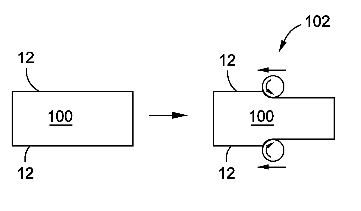
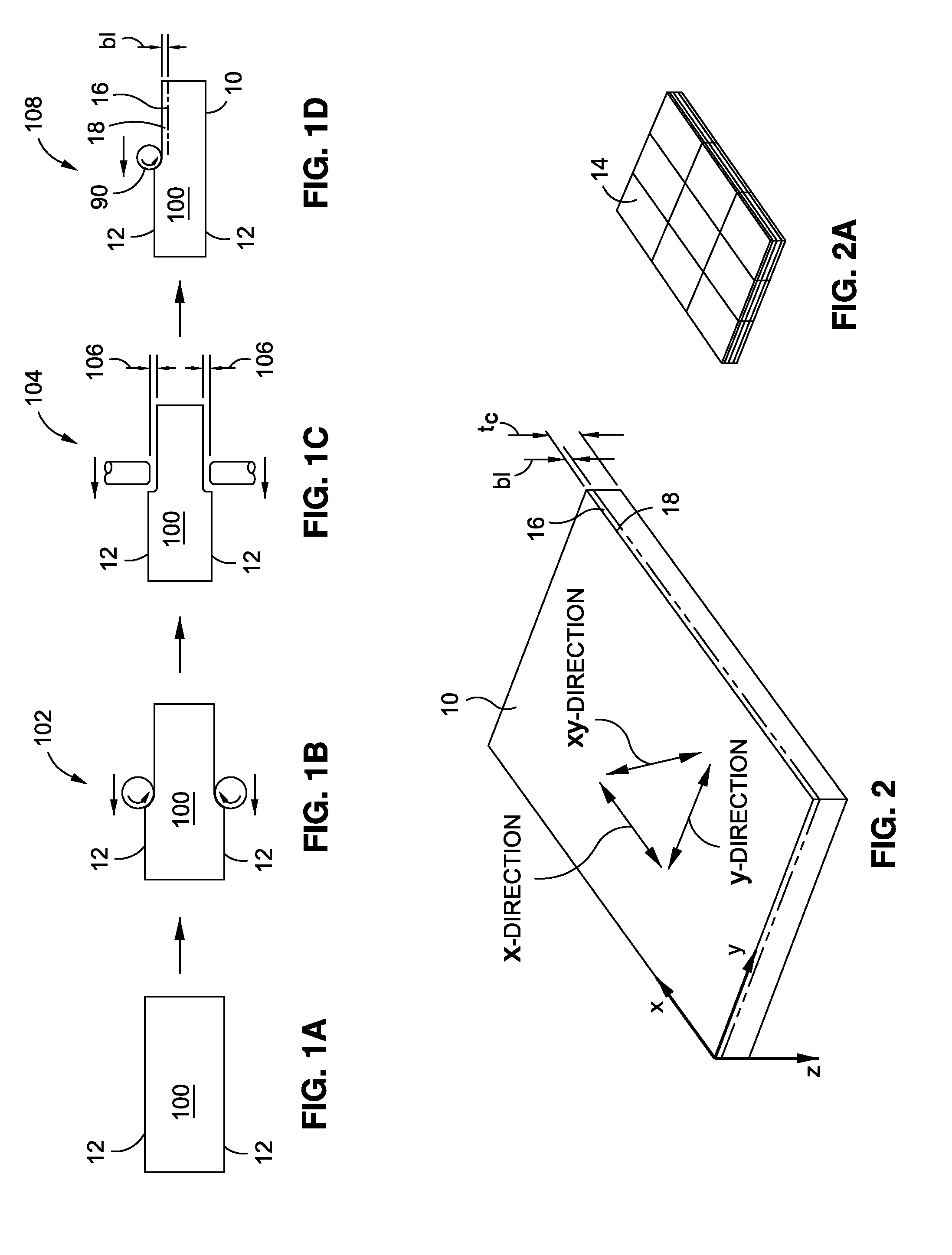
[0051]Referring now to the drawings wherein the showings are for purposes of illustrating preferred and various embodiments of the disclosure, shown in FIGS. 1A-1D is a schematic illustration of a sequence of operations for fabricating a plate coupon 10 (FIG. 2) from plate stock 100 (FIGS. 1A-1D). A selected manufacturing operation 108 (FIG. 1D) may be performed on one of opposing surfaces 12 of the plate coupon 10. In an embodiment, the selected manufacturing operation 108 may comprise a machining operation using a rotary cutting tool 90 as shown in FIG. 1D. The selected manufacturing operation 108 may induce residual stress 18 along the coupon surface 12 as shown in FIG. 1D and FIG. 2. The induced residual stress 18 may be measured in each one of an x-direction, a y-direction and an xy-direction (FIG. 2). Measurements of induced residual stress 18 may be performed by any suitable technique including, but not limited to, x-ray diffraction. The induced residual stress measurements 5...


PUM


Abstract

A method of predicting distortion in a workpiece may include measuring residual stress induced in a coupon surface of a plate coupon by a selected manufacturing operation. The induced residual stress measurements may be fitted to a curve shape function. A moment coefficient may be calculated based upon the fitted induced residual stress measurements. The moment coefficient may be used to calibrate a stress function and corresponding stress magnitude. The calibrated stress function may be applied to a model of the workpiece such that the distortion of the workpiece may be predicted.

Description

STATEMENT RE: FEDERALLY SPONSORED RESEARCH / DEVELOPMENT[0001]This invention was made with Government support under United States Air Force Cooperative Agreement No. FA8650-07-2-5203. The Government has certain rights in this invention.CROSS-REFERENCE TO RELATED APPLICATIONS[0002](Not Applicable)FIELD[0003]The present disclosure relates generally to residual stress induced in a workpiece as a result of a manufacturing operation performed on the workpiece.BACKGROUND[0004]Residual stress may be defined as stress that resides or remains within a workpiece following the application of one or more manufacturing operations. Manufacturing operations that induce residual stress in a workpiece may include any process where heat, pressure and / or energy are applied to the workpiece. For example, a machining operation may be performed on a metallic (e.g., aluminum, titanium) workpiece in order to shape the workpiece into its intended configuration. During the machining operation, a rotating cutti...

Claims


Application Information

Patent Timeline
IPC IPC(8): G01L1/00
CPCG01L1/00G01L5/0047G06F17/5018G06F30/23
Inventor CASTLE, JAMES B.NERVI, SEBASTIANHANCOCK, RANDOLPH B.BOLIN, JARED
Owner THE BOEING CO
Learn More