
Apparatus and method for filling a mold with a liquid material

Active Publication Date: 2014-02-04
KIPE MOLDS
View PDF8 Cites 24 Cited by
  • Summary
  • Abstract
  • Description
  • Claims
  • Application Information

AI Technical Summary

Benefits of technology

The patent text describes a method and apparatus for controlling the filling of a mold with a compressible liquid material in a multi-port direct injection molding system. The invention involves modulating a valve to perform a plurality of pulse cycles during the filling cycle of the mold. Specifically, a first pulse cycle includes moving a throttling member of the valve from a first position to a second position, and then from the second position to a third position. The method achieves improved fill balance control, leading to better quality molded parts.

Problems solved by technology

However, a mold cavity filling at a rate slower than the corresponding designed heat transfer rate poses a risk that the mold material may begin to solidify before the mold is completely full.
This condition of premature curing or solidification is referred to as a “short shot,” and may result in defects in the molded product.
In the alternative, a mold cavity filling at a faster rate than the corresponding designed heat transfer rate poses a risk that the mold material may begin to over-pressurize the mold cavity and overflow the cavity.
This condition of overflowing the mold cavity is referred to as “flash,” and may result in defects in the molded product.
Some molding material properties pose challenges to flow uniformity in multi-port direct injection molding systems.
These problematic material properties include compressibility and non-Newtonian behavior.
Further, pressure does not transmit instantaneously through a compressible liquid.
Shear thinning behavior can be problematic in multi-port, direct injection molding systems because differences in shear energy from flow of the silicone through different channels may cause differences in apparent viscosity among the different channels.
In turn, the differences in apparent viscosity among different channels can cause undesirable non-uniformity in flow through the different channels.
Further, these differences in apparent viscosity can amplify over time because the channels with the highest flow experience the most shear thinning, which may cause the fluid to flow even faster and cause even more non-uniformity among the mold cavity filling rates.
However, the temperature control method is disadvantageous because one must know the extent of the system flow non-uniformity a priori in order to choose the control heater set points.
Further, the thermal capacitance of a multi-runner injection system can result in slow temperature response of the liquid material, thereby causing production delays.
Moreover, the temperature control method is not considered applicable to thermal set materials because adding heat to the thermal set material upstream of the mold could cause undesirable material curing upstream of the mold or premature curing within a mold cavity.
However, the flow distribution control approaches involving mechanical chokes, differential valve throttling, and differential valve opening delays all suffer from a common disadvantage as differential temperature control, namely that the nature and degree of imbalance in the system must be characterized a priori in order to implement the control.
Indeed, trial and error is required to implement correctly sized manual chokes in the correct locations, or to select the correct biases in valve opening positions, or to select the correct valve opening delays to improve the balance a multi-port direct injection molding system.
Further, the flow resistance tailoring scheme that improves the balance for one machine paired with one mold may not balance the flows in another machine paired with the same mold or the same machine paired with different mold.
While flow balance may be improved, the liquid material flowing through the restricted flow paths may be heated as it is restricted, thereby introducing runner-to-runner thermal variations which can lead to undesirable pack characteristics in the molded parts.
In addition, the valve gate control systems that delay valve openings for the faster flowing channels may introduce differences in fill times, which can affect shrinkage conditions and therefore part quality.

Method used


Image

  • Apparatus and method for filling a mold with a liquid material
  • Apparatus and method for filling a mold with a liquid material
  • Apparatus and method for filling a mold with a liquid material

Examples


Embodiment Construction

[0049]Referring now to the drawings, wherein like reference numerals designate identical or corresponding parts throughout the several views.

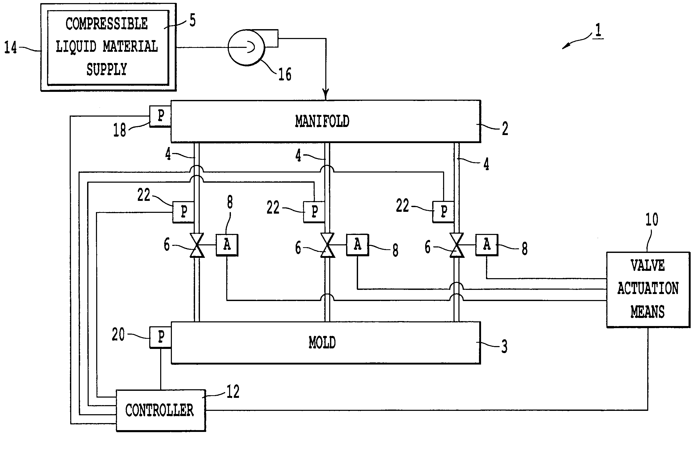
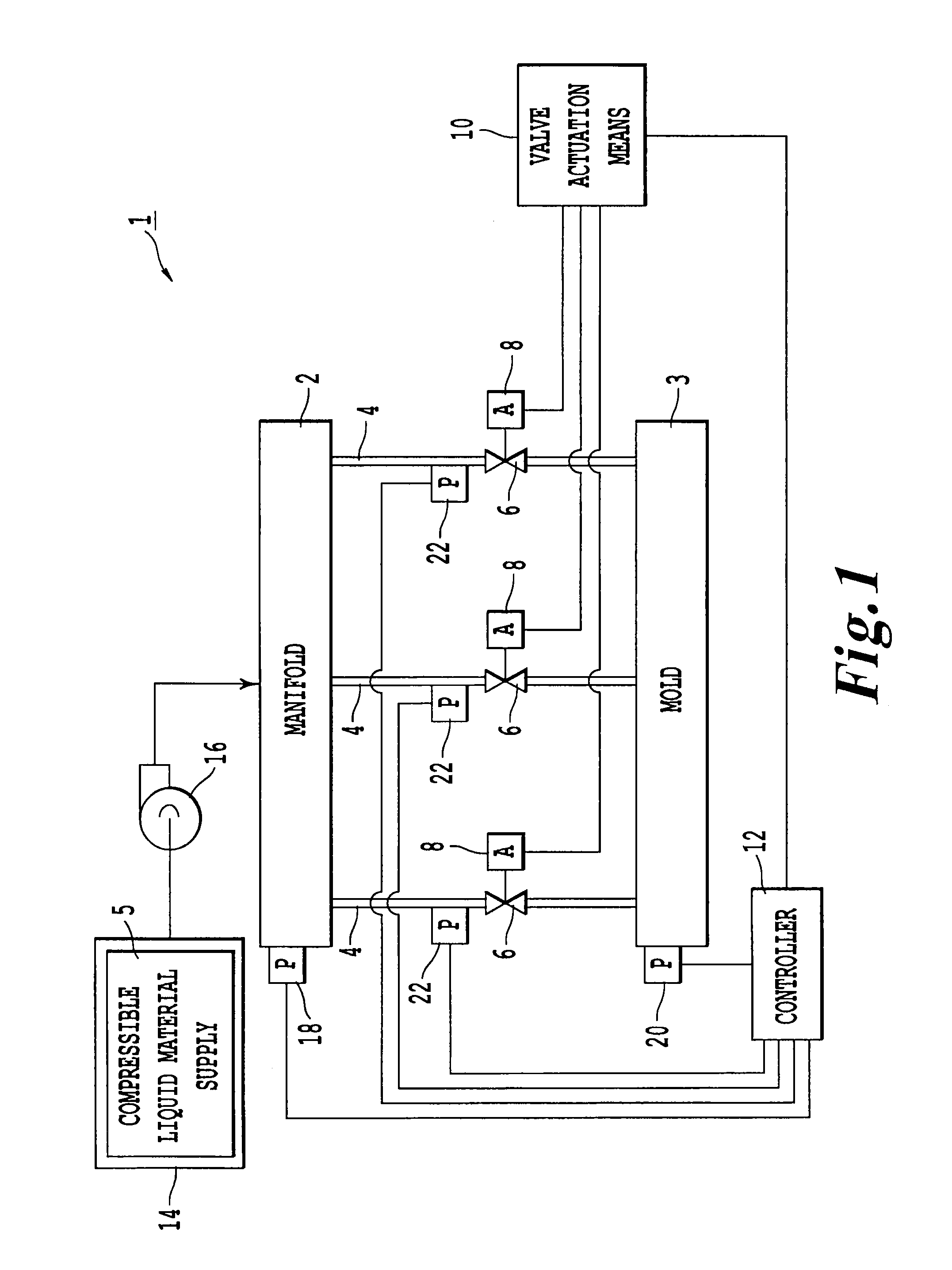
[0050]FIG. 1 shows an exemplary embodiment of an apparatus 1 for filling a mold 3 with a compressible liquid material 5. The apparatus 1 includes a manifold 2 that may be in fluid communication with a mold 3 through a plurality of runners 4. Although FIG. 1 shows three runners 4, the apparatus 1 may include any number of runners 4 greater than or equal to two. Further, the apparatus 1 may include one or more molds 3 in fluid communication with the same manifold 2, where each mold may include one or more mold cavities therein. Moreover, a single mold 3 cavity may be in fluid communication with one or more runners 4, and a single runner 4 may be in fluid communication with one or more mold 3 cavities.

[0051]The apparatus 1 further includes at least one valve 6 disposed in the at least one runner 4, where each valve 6 is in fluid communication with...


PUM

PropertyMeasurementUnit
Fractionaaaaaaaaaa
Timeaaaaaaaaaa
Timeaaaaaaaaaa

Abstract

A method for filling a mold with a compressible liquid material is disclosed. The mold is connected to a manifold via a plurality of runners, with at least one valve disposed in at least one of the plurality of runners. A controller is configured to pressurize the manifold with the liquid material, and modulate the at least one valve to perform a plurality of pulse cycles during one filling cycle of the mold. A pulse cycle includes adjusting an aperture of the valve from a first position to a second position, and adjusting the aperture of the valve from the second position to a third position, where the aperture corresponding to the second position is larger than the aperture corresponding to the first position, and the aperture corresponding to the third position is smaller than the aperture corresponding to the second position.

Description

BACKGROUND OF THE INVENTION[0001]1. Field of the Invention[0002]The present invention relates to apparatus, software, and methods for filling a mold with a liquid material. More particularly, the present invention relates to apparatus, software, and methods for filling a mold with a liquid material by pulsing the liquid material flow.[0003]2. Description of the Related Art[0004]Injection molding is a method for manufacturing parts using a material that is a liquid in an uncured state, and that may be transformed into a solid by a curing or freezing process within a mold. Two broad classes of molding materials used in injection molding are thermal plastic materials and thermal set materials. Thermal set materials remain liquid at relatively low temperatures, and through application of heat over time (i.e., curing), the chemical composition of thermal set materials can be altered to yield a solid. Thermal plastic materials, on the other hand, are solid at relatively low temperatures, ...

Claims


Application Information

Patent Timeline
IPC IPC(8): B29C45/76
CPCB29C45/76B29C2945/76561B29C2945/76862B29C2945/76568B29C2945/76943B29C2945/76752B29K2083/005B29C2945/76859B29K2221/003B29C2945/76006B29C45/77B29C2945/76545
Inventor KIPE, GEORGEWIRTH, KASPAR
Owner KIPE MOLDS
Learn More