System and method for aerodynamic flow control

a technology of aerodynamic flow control and system, applied in the field of system and, can solve the problems of always deploying passive devices and reducing the efficiency of air vehicles on which they are used

Active Publication Date: 2014-02-04
TEXTRON INNOVATIONS
View PDF31 Cites 12 Cited by
  • Summary
  • Abstract
  • Description
  • Claims
  • Application Information

AI Technical Summary

Problems solved by technology

The disadvantage of passive devices like these is that such passive devices are always deployed, even when not needed.
Under such circumstances passive SVGs add parasitic drag that lowers the efficiency of air vehicles on which they are used.

Method used


Image

  • System and method for aerodynamic flow control
  • System and method for aerodynamic flow control
  • System and method for aerodynamic flow control

Examples


Embodiment Construction

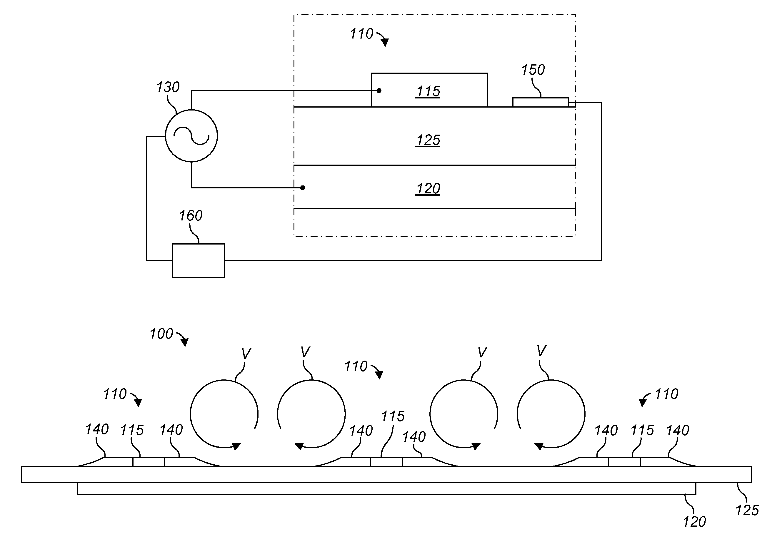
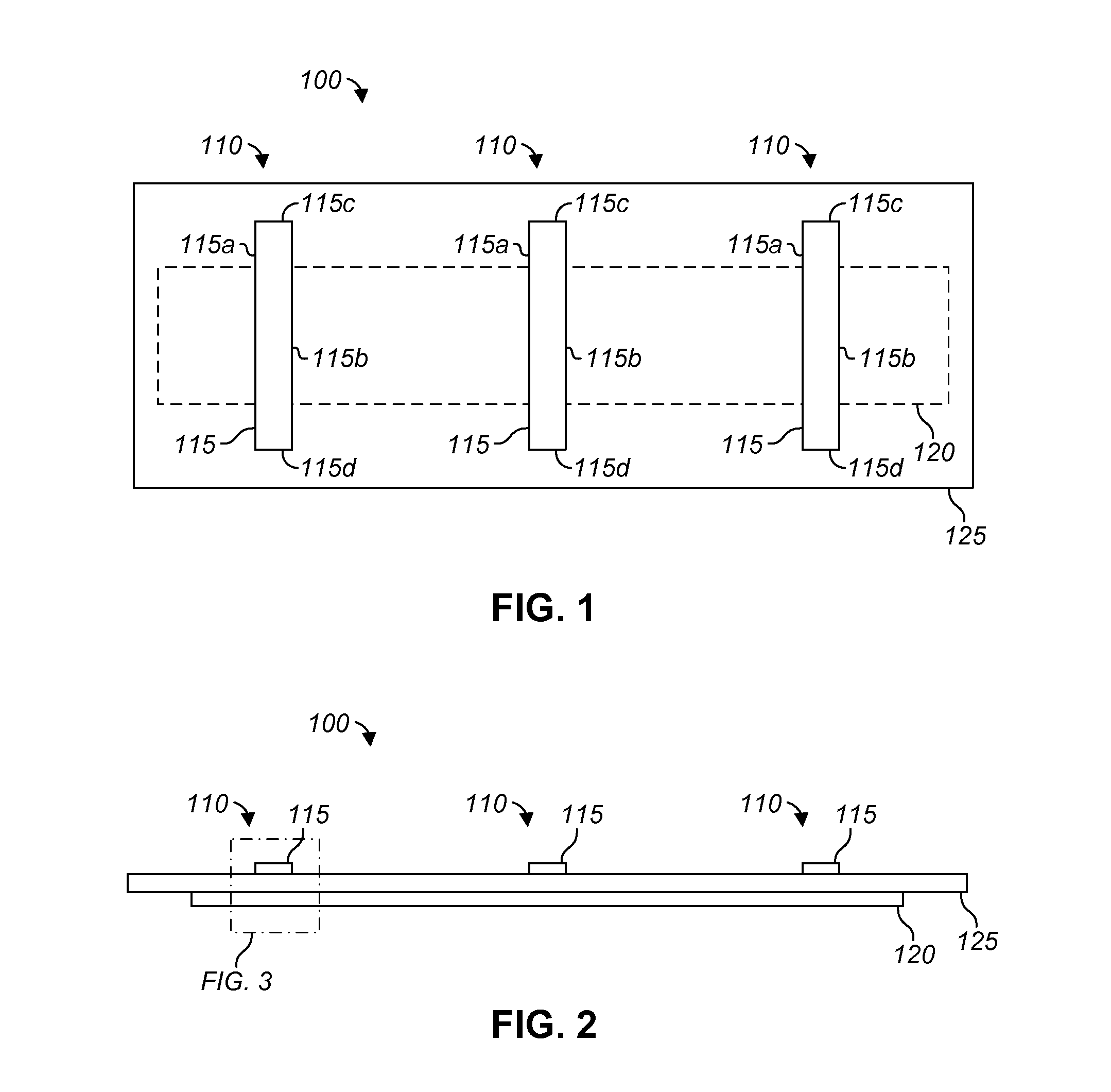
[0012]Referring to FIGS. 1 and 2, FIG. 1 shows a plan view of a vortex generator system 100, and FIG. 2 shows a front view of the vortex generator system 100. The vortex generator system 100 comprises a plurality of plasma streamwise vortex generators (PSVGs) 110. While three PSVGs 110 are shown, alternative embodiments can include any number of PSVGs 110. PSVG 110 comprises a first electrode 115 and a second electrode 120 (shown in phantom in FIG. 1). PSVG 110 also includes a dielectric layer 125 disposed between the first and second electrodes 115 and 120. Although electrodes 115 are shown as extending from the surface of dielectric layer 125, it should be appreciated that the electrodes 115 can be formed of a relatively thin material, and / or can be provided in respective recesses in the surface of dielectric layer 125 so as to be partially or completely flush with the upper surface of dielectric layer 125. In some embodiments, the electrodes 115 can be exposed to the surrounding ...


PUM

PropertyMeasurementUnit
angleaaaaaaaaaa
angleaaaaaaaaaa
length dimensionaaaaaaaaaa

Abstract

A vortex generator system comprises one or more plasma streamwise vortex generators (PSVGs) or plasma wedge vortex generators (PWVGs). The PSVGs and PWVGs each comprises a first electrode and a second electrode separated by a dielectric layer. The first electrode extends in a longitudinal direction. The PSVGs and PWVGs can be installed on a surface arranged to receive airflow in a certain flow direction. The PSVGs have a rectangular first electrode is exposed and extends at least somewhat parallel to the expected flow direction, whereas the first electrode of the PWVGs is more triangular in shape. When an AC voltage is applied to the first and second electrodes, a plasma forms along edges of the first electrode. The plasma imposes a body force in a cross-flow direction, which induces a cross-flow velocity that, in combination with the mean flow, produces streamwise-oriented counter-rotating vortices.

Description

TECHNICAL FIELD[0001]The present application relates to vortex generators. In particular, the present application relates to vortex generators mounted to substantially continuous aerodynamic surfaces to energize boundary layer air to at least partially alleviate the onset of separated flow over the surfaces.DESCRIPTION OF PRIOR ART[0002]With proper design, streamwise vortex generators (SVGs), such as passive delta-shaped tabs, can generate longitudinal vortices that can be effective in maintaining attached flow over a surface, such as the wing of an aircraft. The disadvantage of passive devices like these is that such passive devices are always deployed, even when not needed. Under such circumstances passive SVGs add parasitic drag that lowers the efficiency of air vehicles on which they are used.[0003]Hence, there is a need for improvements to vortex generator systems and processes.BRIEF DESCRIPTION OF THE DRAWINGS[0004]FIG. 1 shows a plan view of a vortex generator system;[0005]FI...

Claims


Application Information

Patent Timeline
Patent Type & Authority Patents(United States)
IPC IPC(8): B64C23/00
CPCB64C2230/12F15D1/12Y02T50/166B64C23/005Y02T50/10
Inventor CORKE, THOMASTHOMAS, FLINTSHATZMAN, DAVIDWOOD, TOMMIE
Owner TEXTRON INNOVATIONS
Why Eureka
Try Eureka