
Enclosure, assembly and method for reducing noise from a pump and mass spectrometry system

a vacuum pump and mass spectrometry technology, applied in the direction of machine supports, particle separator tubes, sound producing devices, etc., can solve the problems of high vacuum pump noise, complex and costly, and inconvenient viewing of boxes, etc., to achieve the effect of convenient viewing

Inactive Publication Date: 2014-02-04
THERMO FISHER SCI BREMEN
View PDF16 Cites 7 Cited by
  • Summary
  • Abstract
  • Description
  • Claims
  • Application Information

AI Technical Summary

Benefits of technology

The solution effectively reduces noise by up to 90% while being simple, cost-effective, and easy to maintain, with improved accessibility and cooling airflow, making it suitable for roughing pumps used in mass spectrometry systems.

Problems solved by technology

Certain types of vacuum pump in both industrial and laboratory environments generate a considerable amount of noise thereby making working conditions in their vicinity less comfortable.
Many types of higher vacuum pumps do not work well at atmospheric pressure so that a roughing pump is needed to provide a low vacuum in which the higher vacuum pump can work to achieve the higher vacuum.
The pump noise is reduced but the box is necessarily bulky, complex and costly because sufficient ventilation must be provided with the box to prevent overheating of the pump.
The ventilation is provided by fans, which require a power supply (thereby adding to the total power consumption) and maintenance and they are a source of noise themselves.
Moreover, full enclosure by the box makes the pump harder to reach which, in turn, makes maintenance of the pump more difficult.

Method used


Image

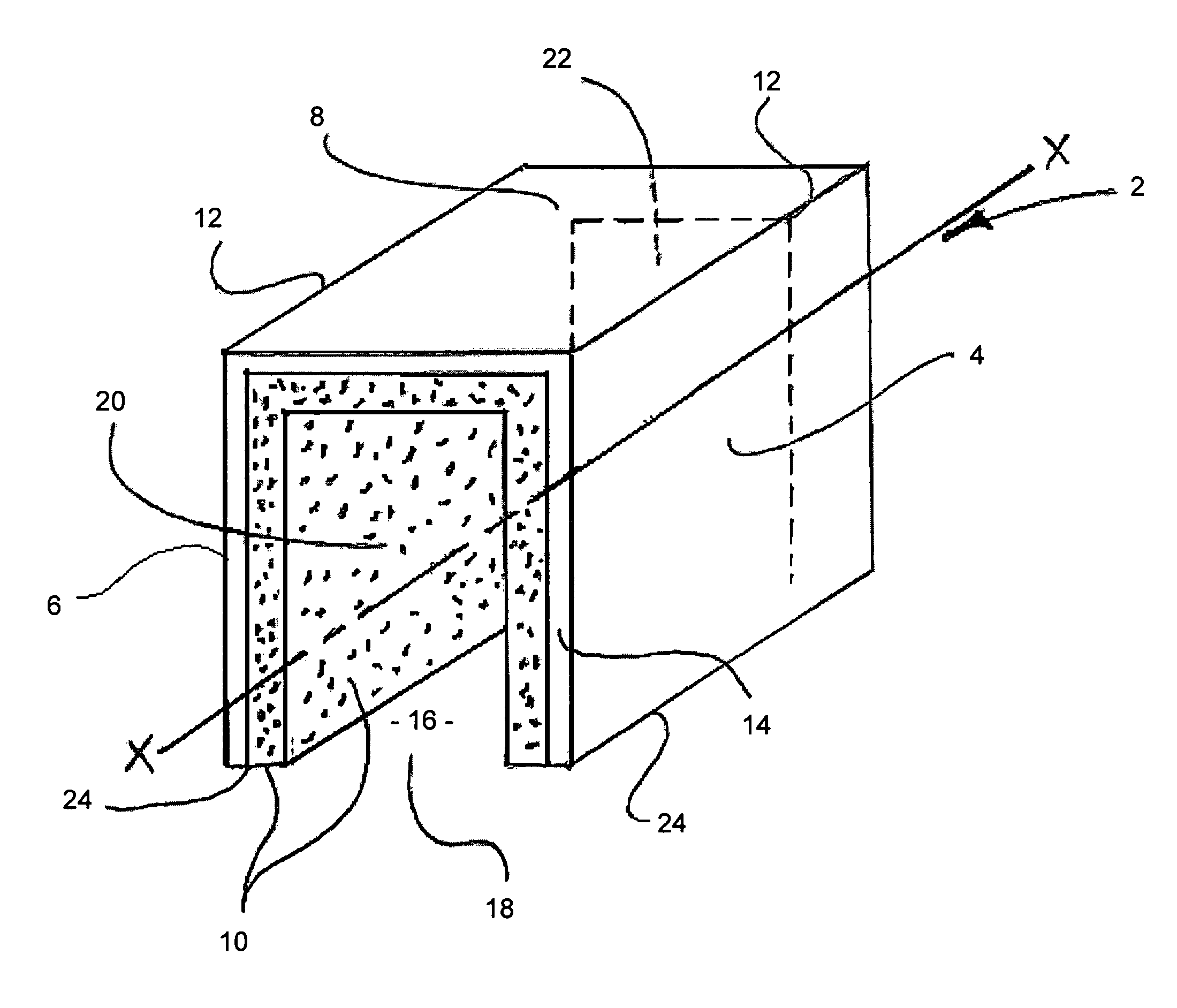
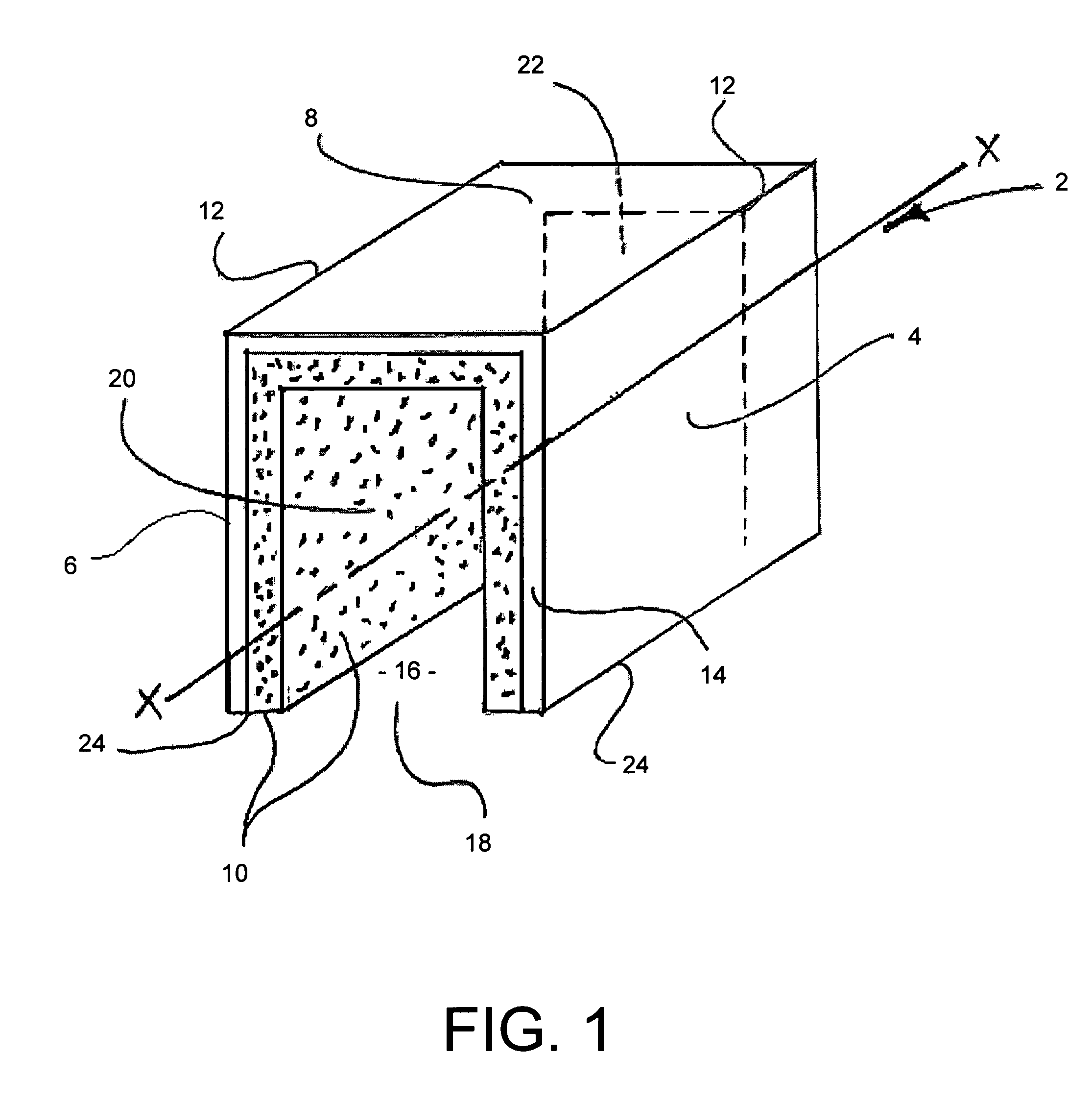
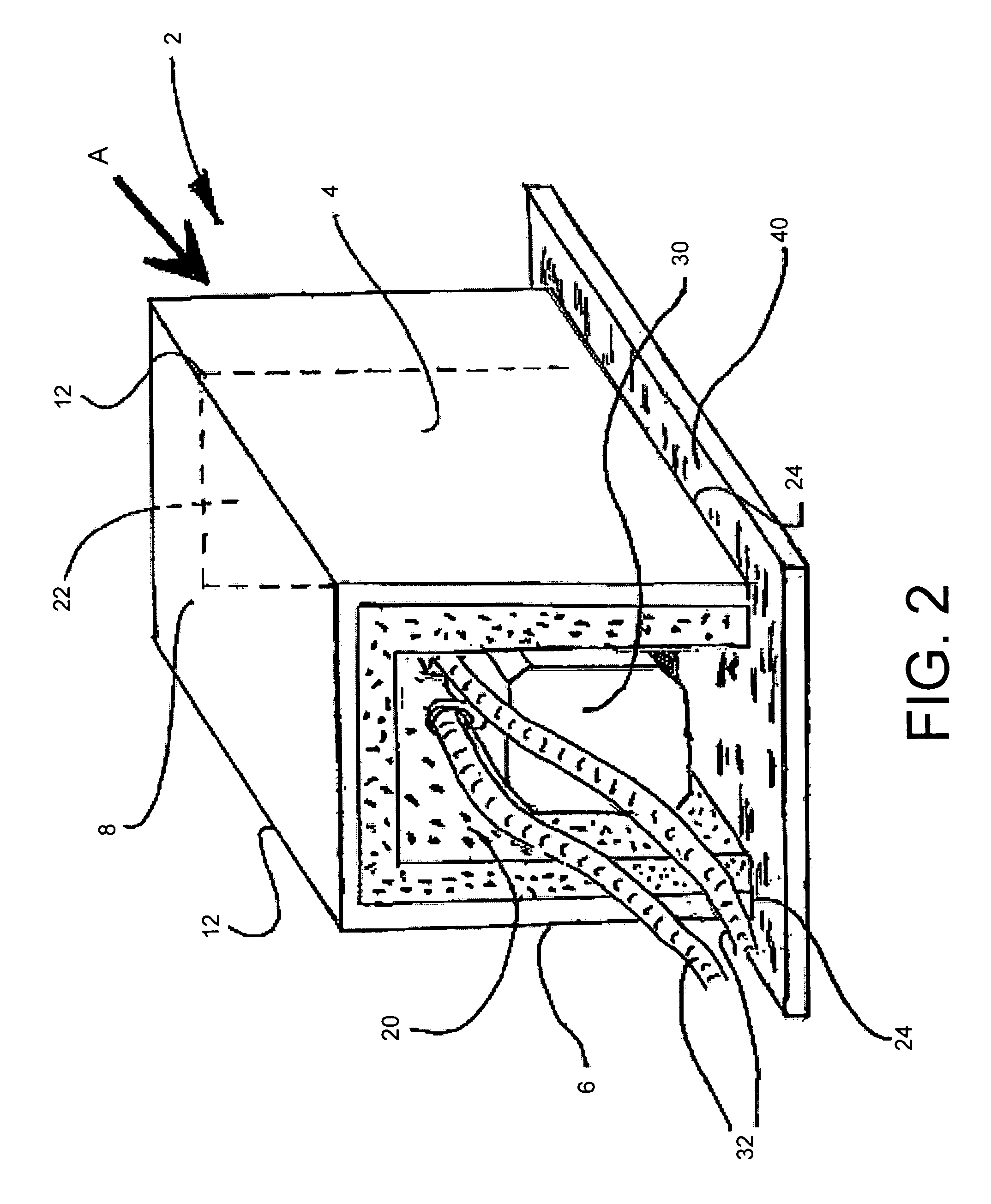
  • Enclosure, assembly and method for reducing noise from a pump and mass spectrometry system
  • Enclosure, assembly and method for reducing noise from a pump and mass spectrometry system
  • Enclosure, assembly and method for reducing noise from a pump and mass spectrometry system

Examples


Embodiment Construction

[0014]It will be appreciated that herein the reference to a pump does not limit the scope of the present invention to one pump only but instead it means at least one pump, e.g. two or more pumps may be enclosed by the enclosure. In the case of enclosure of two or more pumps, the pumps may be located in any arrangement with respect to each other (e.g. in-line (end-to-end), side-by-side, or any other arrangement). The pump which is enclosed by use of the present invention is preferably a roughing pump. The vacuum typically achievable in use by the roughing pump is a low vacuum, e.g. of pressure not less than 1×10⁻³ mbar, preferably not less than 1×10⁻⁴ mbar. The roughing pump is typically a rotary pump. Examples include a rotary vane pump, a roots pump and a rotary piston pump. Other types of roughing pump include a scroll pump, a membrane pump and the like. Such pumps include pumps made by manufacturers such as Edwards and Leybold, for example. Specific pump models include, without a...


PUM


Abstract

The invention provides a noise reducing enclosure for reducing the noise from a vacuum pump, e.g. a roughing pump of a high vacuum system, the vacuum pump having a long axis and the enclosure comprising a noise dampening material and being shaped to radially enclose the vacuum pump along its long axis and being axially open at each end. Airflow is permitted through the enclosure in use and optional integrated cooling means on the pump may assist cooling of the pump. The invention also provides an assembly of the pump and enclosure, a method for reducing the noise from a vacuum pump using the enclosure and a mass spectrometry system comprising: a mass spectrometer having one or more chambers therein which in operation are held under vacuum; and a vacuum pumping system for producing said vacuum, the vacuum pumping system comprising at least one vacuum pump which has a long axis and wherein the mass spectrometry system further comprises a noise reducing enclosure for radially enclosing the vacuum pump along its long axis, wherein the enclosure is axially open at each end.

Description

FIELD OF THE INVENTION[0001]The invention relates generally to an enclosure, an assembly and a method for reducing noise from a vacuum pump, as well as a mass spectrometry system.BACKGROUND OF THE INVENTION[0002]Certain types of vacuum pump in both industrial and laboratory environments generate a considerable amount of noise thereby making working conditions in their vicinity less comfortable. Examples of pumps which are in particular need of noise reduction include roughing pumps, i.e. pumps employed to achieve a low vacuum, e.g. typically not less than 1×10⁻³ mbar. Roughing pumps are often used in combination with higher vacuum pumps, e.g. turbomolecular pumps. Many types of higher vacuum pumps do not work well at atmospheric pressure so that a roughing pump is needed to provide a low vacuum in which the higher vacuum pump can work to achieve the higher vacuum. Rotary pumps, e.g. rotary vane pumps, are commonly used roughing pumps in need of noise reduction. Other types of roughi...

Claims


Application Information

Patent Timeline
Patent Type & Authority Patents(United States)
IPC IPC(8): G10K11/16
CPCF04C25/02F04C2270/12F04C2240/30F16M1/00F04B53/002F04D29/664F04C29/066F04C29/06
Inventor SEEDORF, RONALD
Owner THERMO FISHER SCI BREMEN
Learn More