
Laser-marked multi-component assemblies, kits, and related methods

a multi-component, laser-marked technology, applied in the direction of vacuum evaporation coating, flooring, manufacturing tools, etc., can solve the problems of poor efficiency, difficult seam or spacing between components, and inability of laser marking equipment to handle and mark over the large expansive surface of an assembled multi-component structur

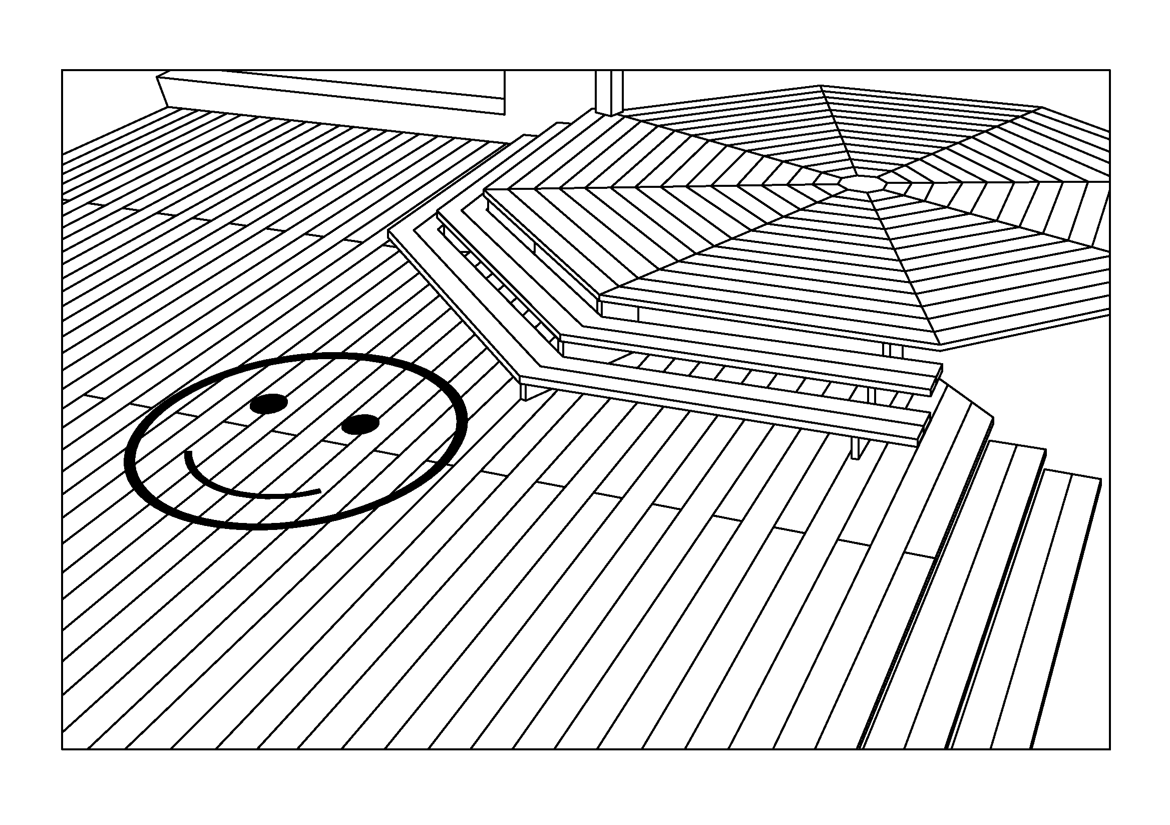
Inactive Publication Date: 2014-02-04
MASONITE CORP
View PDF54 Cites 23 Cited by
  • Summary
  • Abstract
  • Description
  • Claims
  • Application Information

AI Technical Summary

Problems solved by technology

One of the difficulties involved in laser marking a graphic design on a multi-component structure post-assembly is that laser marking equipment is typically not capable of handling and marking over the large expansive surface of an assembled multi-component structure, such as floor and wall surfaces.
Poor efficiency is another difficulty that arises when attempting to laser mark the expansive surface of an assembled multi-component structure.
Still another difficulty involved in laser making an expansive surface of an assembled multi-component structure is difficulty in compensating for seams or spacing between components, such as in the case of seams between adjacent wall panels or spacing between deck planks.

Method used


Image

  • Laser-marked multi-component assemblies, kits, and related methods
  • Laser-marked multi-component assemblies, kits, and related methods
  • Laser-marked multi-component assemblies, kits, and related methods

Examples


Embodiment Construction

[0018]Reference will now be made in detail to exemplary embodiments and methods of the invention as illustrated in the accompanying drawings, in which like reference characters designate like or corresponding parts throughout the drawings. It should be noted, however, that the invention in its broader aspects is not limited to the specific details, representative devices and methods, and illustrative examples shown and described in this section in connection with the exemplary embodiments and methods. The invention according to its various aspects is particularly pointed out and distinctly claimed in the attached claims read in view of this specification, and appropriate equivalents.

[0019]The term “laser mark” used herein means to irradiate a component, such as a PVC-wood composite, with a laser beam to form a graphic design. In the course of marking, the laser beam causes a visually perceptible change to the component surface. The change may involve removal, ablation, etching, engr...


PUM

PropertyMeasurementUnit
angleaaaaaaaaaa
lengthaaaaaaaaaa
widthaaaaaaaaaa

Abstract

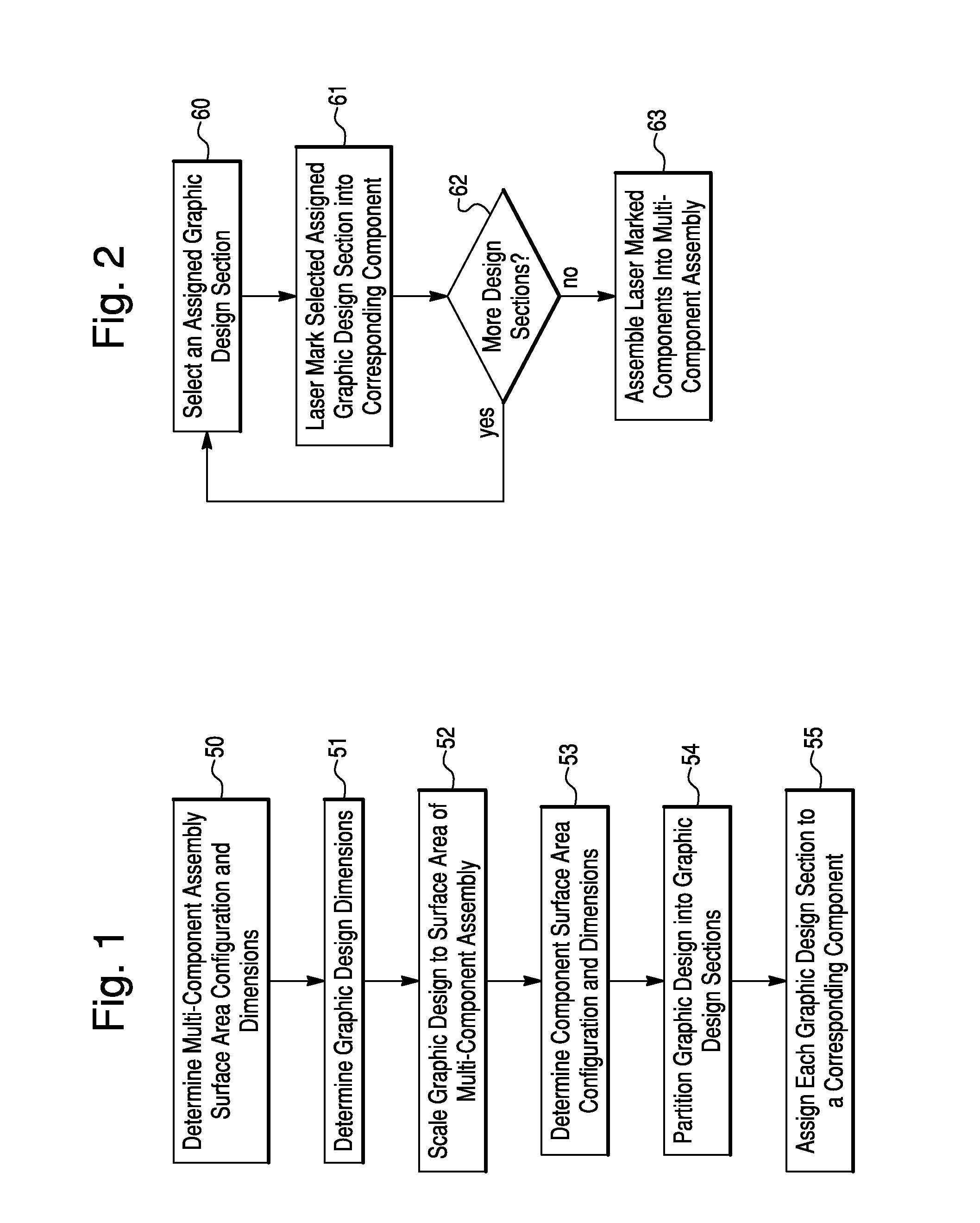
A method is provided of laser marking a graphic design in an unassembled multi-component structure. A graphic design to be laser marked in a multi-component structure is partitioned into a plurality of graphic design sections, with each of the graphic design sections being assigned to a corresponding component of the multi-component structure. The graphic design sections are laser marked in their corresponding components of the multi-component structure while the multi-component structure is in an unassembled state. The laser-marked components are adapted for assembly together into an assembled state in which the multi-component structure has a viewable expansive surface with the graphic design sections collectively simulating an overall appearance of a graphic design spanning across the corresponding components of the multi-component structure. A kit for assembling laser-marked components into a multi-component structure is also provided.

Description

CROSS-REFERENCE TO RELATED APPLICATION AND CLAIM OF PRIORITY[0001]This application claims the benefit of priority under 35 U.S.C. §119(e) to U.S. Provisional Patent Application No. 61 / 090,796 filed Aug. 21, 2008 entitled “Laser-Marked Multi-Component Assemblies, Kits, and Related Methods,” the complete disclosure of which is incorporated herein by reference.FIELD OF THE INVENTION[0002]The present invention relates to laser-marked multi-component assemblies, laser-marked components, component assembly kits, and methods of laser-marking and assembling the components to form laser-marked multi-component assemblies such as building structures.BACKGROUND OF THE INVENTION[0003]Large assemblies such as building structures often present expansive viewable surface areas that may serve as a canvas for application of a graphic design. Graphic designs include patterns, non-patterns, discrete graphic elements, and the like. These graphic designs can be applied to an assembly such as a building s...

Claims


Application Information

Patent Timeline
Patent Type & Authority Patents(United States)
IPC IPC(8): C03C15/00B27H1/00B23K26/00E04F13/00
CPCE04F13/0871B44C3/123B44C1/228E04F13/00
Inventor RUGGIE, MARKCOGHLAN, HENRYHEUSER, HALLIECARTER, CHASE
Owner MASONITE CORP
Learn More