
Protective frame for mobile communication device

a mobile communication and protective frame technology, applied in the direction of electrical apparatus construction details, electrical apparatus casings/cabinets/drawers, instruments, etc., can solve the problems of increased power consumption, increased screen size of new generation smart-phones and tablet computers, and increased risk of crashes or scratches, so as to reduce the size and weight of the protective frame, shorten the protective frame, and facilitate assembly

Inactive Publication Date: 2014-01-21
TAER INNOVATION
View PDF4 Cites 26 Cited by
  • Summary
  • Abstract
  • Description
  • Claims
  • Application Information

AI Technical Summary

Benefits of technology

[0008]An objective of the invention is to provide a protective frame for mobile communication device, which allows an auxiliary battery to be freely combined with, or to be detached from, the protective frame, thereby offering the user with preferable options and application flexibility.
[0009]Another objective of the invention is to provide a protective frame for mobile communication device, which effectively implements carriage and replacement of multiple sets of auxiliary batteries.
[0010]Yet another objective of the invention is to provide a protective frame for mobile communication device, which allows the use of the protective frame solely to provide protection when additional power source is not required, thereby enabling convenient protection of the mobile communication device.
[0011]Still another objective of the invention is to provide a protective frame for mobile communication device, which facilitates convenient assembly and disassembly as well as handy operation.
[0013]By virtue of the aforementioned structural arrangement, it can be appreciated that a revolutionary change has been achieved by means of the protective frame disclosed herein. Through the structural arrangement between the main frame body and the sliding element, the protective frame can provide an architecture for freely retracting and extending. When the auxiliary battery is needed, it is possible to position the sliding element at the stretched auxiliary power supply position, so as to accommodate the above-said auxiliary battery. In the case where the auxiliary battery is not required, it is possible to shorten the protective frame by positioning the sliding element at the retracted protection position, thereby minimizing the size and weight of the protective frame.
[0014]By way of the sophisticated structural arrangement between the auxiliary battery and the protective frame disclosed herein, the invention enables convenient assembling of the auxiliary battery to the protective frame, as well as convenient disassembling of the auxiliary battery from the protective frame. When the auxiliary battery is removed, the size of the protective frame can be adjusted by a retraction operation. Therefore, when the mobile communication device is sufficiently charged with power or else the auxiliary battery has run out of electricity, it is possible to take off the auxiliary battery at all time, thereby saving the space and weight for carrying the mobile communication device. Meanwhile, under the condition that the mobile communication device is solely protected by the protective frame, the auxiliary battery can be removed and recharged independently. Moreover, once the auxiliary battery becomes aged and damaged, it is also possible to replace it with a new one without substituting it along with the protective frame, thereby conforming to the trend of environment protection. Especially, if the user heavily relies on the mobile communication device or the mobile communication device itself is extremely power consumptive and suffers from a short standby duration, the invention could provide an appropriate solution which allows the user to prepare a number of auxiliary batteries and have them fully recharged beforehand for timely replacement. In this way, the application time of the mobile communication device can be significantly increased, so as to eliminate the trouble of power depletion. As such, the aforementioned objectives can be completely achieved. The problem of inconvenience in using the conventional protective frame for mobile communication devices can be successfully resolved and a protective frame for mobile communication device offering features more close to the user's habits can be also realized.

Problems solved by technology

However, such developments in smart-phones and tablet computers lead to an increase in power consumption as compared to conventional communication-only electronic devices.
Furthermore, to facilitate graphic data presentation, the screen size of new generation smart-phones and tablet computers becomes bigger and, thus, vulnerable to crashes or scratches.
As a consequence, these two items are inseparable from each other, thus causing the following drawbacks.
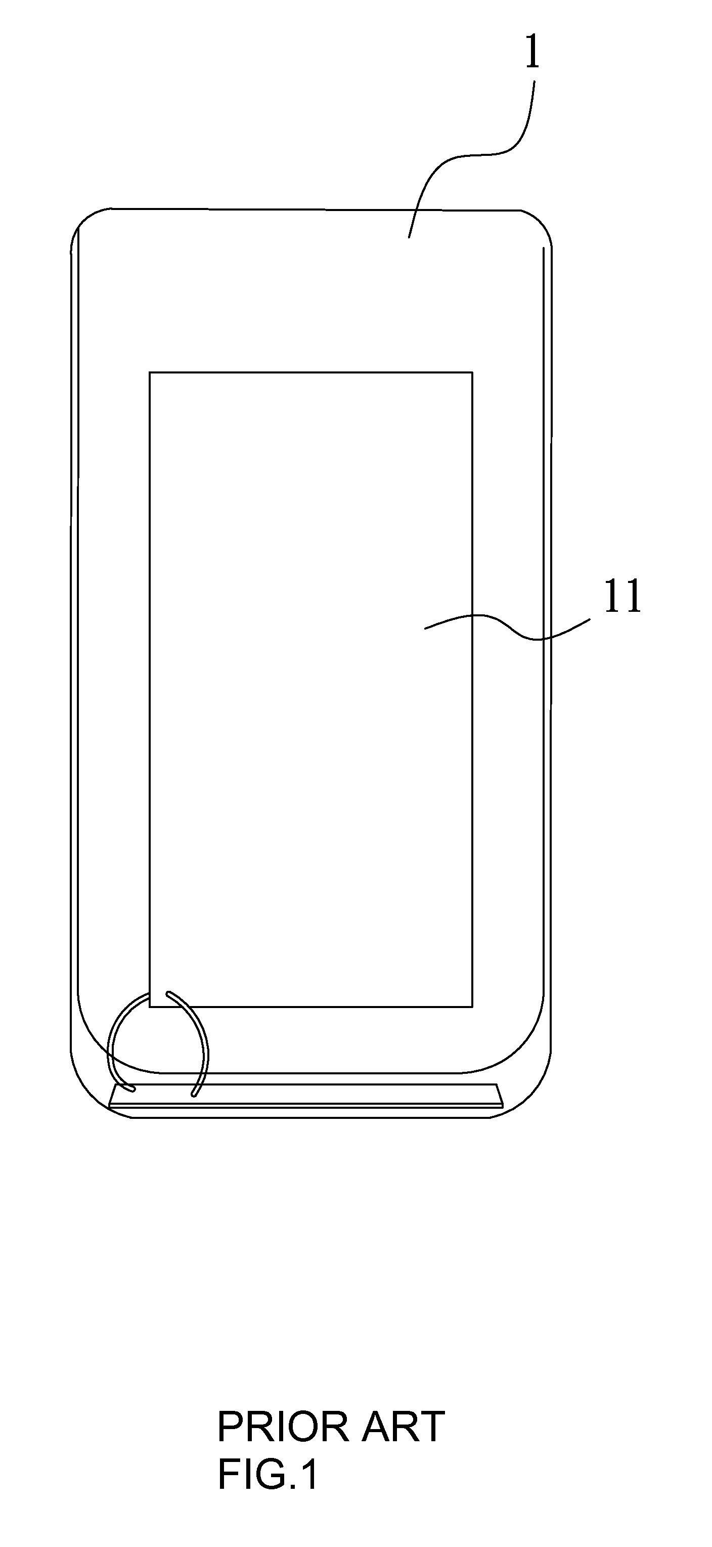
First, once the auxiliary rechargeable battery 11 has run out of electricity, it is inevitable to uninstall it along with the protective case from the mobile communication device for recharging.
If the protection function is chosen to be retained, the battery still need be carried along and undesirably add extra burden even it is already known that the auxiliary rechargeable battery cannot supply power.
Meanwhile, if the user chooses to take off the auxiliary rechargeable battery for recharging, then the protective case need be detached as well and the original objective of protection for the mobile communication device may not be achieved.
Moreover, with such an inseparable design of case body along with the auxiliary battery, in case that the original battery of the mobile communication device itself is already well charged, the user is unable to simply select the protection feature alone and still has to carry an additional auxiliary rechargeable battery.
The design would causes inconvenience for extra weight, even though the user may feel reluctant to carry the auxiliary battery.
That it, although extra electric power is not required, the user is nonetheless forced to bring the auxiliary rechargeable battery, otherwise the protective case cannot be applied to the mobile communication device.
However, such a situation is repugnant to user's demand for purchase, and also contrary to the initial goal of the product design.
From the above-said descriptions, it can be seen that the user will inevitably face a dilemma of choice: whether or not to purchase a protective case that is provided with an auxiliary rechargeable battery.
Such a design apparently fails to fulfill the actual need of users and appears to be quite unfriendly to the users.
For example, if a traveler carries a high power consumptive device, such as a mobile phone or a tablet computer along a trip where power recharging may be inconvenient, it is pretty logical that a single auxiliary rechargeable battery would be insufficient for providing power to the device.
However, this approach would be hindered in the case where the auxiliary rechargeable battery cannot be detached from the protective case.
This situation completely reveals the inconvenience of the design.
A similar problem also exists in case of battery failure as the auxiliary rechargeable battery in the conventional design cannot be replaced.
The usability of the protective case ends when the auxiliary rechargeable battery is ruined.
However, if more serious problems like battery fluid leakage occur, the user will have to discard the battery in conjunction with the protective case, or else the mobile communication device or the user may be adversely influenced.

Method used


Image

  • Protective frame for mobile communication device
  • Protective frame for mobile communication device
  • Protective frame for mobile communication device

Examples


Embodiment Construction

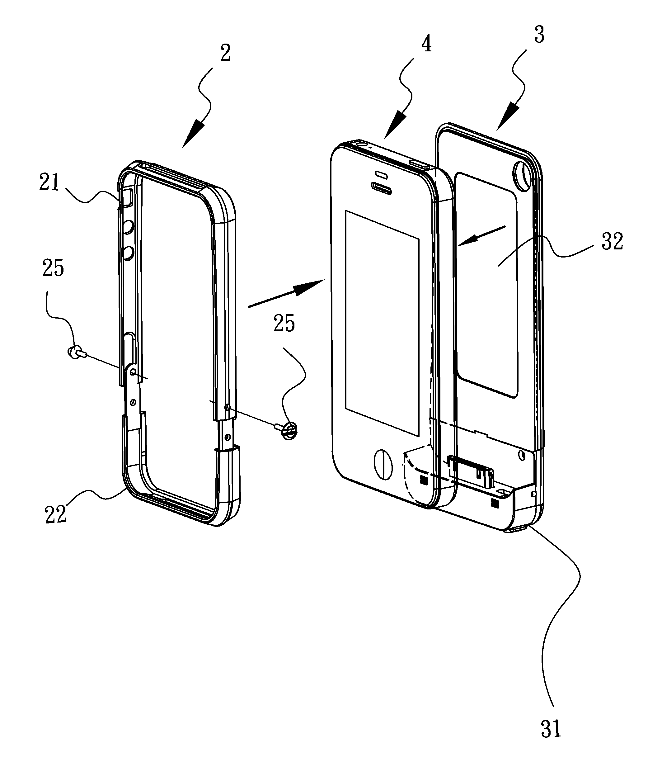
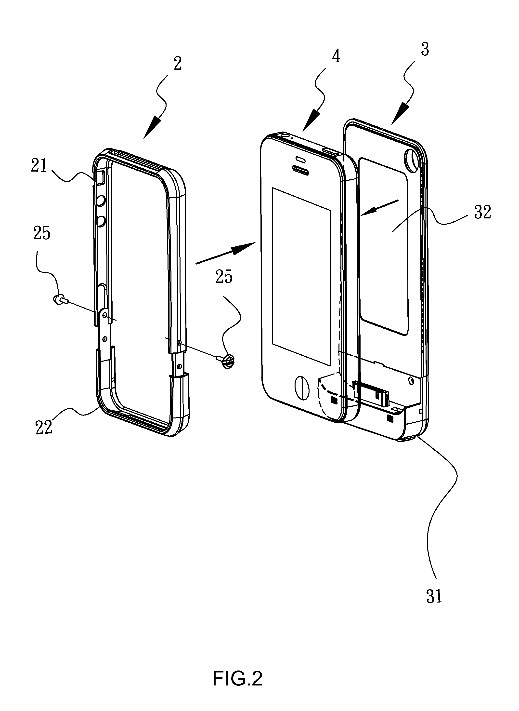
[0026]The invention discloses a protective frame for mobile communication device, wherein the mobile communication device described in the embodiment disclosed herein is exemplified as a mobile phone provided with a power charging port. FIGS. 2 and 3 are the front and rear side diagrams showing the assembling of a retractable frame body 2 and an auxiliary battery 3 into the protective frame according to the invention, wherein the retractable frame body 2 and the auxiliary battery 3 sandwich a mobile communication device 4 from left and right sides. The auxiliary battery 3 in this embodiment consists of two parts. The upper portion of the auxiliary battery 3 is configured as a power storing part 32, which constitutes a main body of the auxiliary battery 3. As shown in FIG. 2, the mobile communication device 4 has a front side for displaying images and a back side opposite to the front side, and the power storing part 32 is adapted to cover the back side of the mobile communication de...


PUM


Abstract

The invention relates to a protective frame for a mobile communication device having a power charging port. The protective frame has a retractable frame body, including a main frame body; a sliding element for reciprocatingly sliding along a direction with respect to the main frame body between a retracted protection position where the mobile communication device is fixedly framed by the retractable frame body and a stretched auxiliary power supply position; and a fastening element for fixing the sliding element with respect to the main frame body at the retracted protection position and the stretched auxiliary power supply position. The protective frame also includes an auxiliary battery adapted for being detachably installed in the retractable frame body and electrically connected to the power charging port of the mobile communication device, when the sliding element are fixed with respect to the main frame body at the stretched auxiliary power supply position.

Description

BACKGROUND OF THE INVENTION[0001]1. Field of the Invention[0002]The present invention generally relates to a protective frame for a mobile communication device and, more particularly, to a protective frame provided with an auxiliary battery and adapted to be used with a mobile phone.[0003]2. Description of Related Art[0004]Significant advancement in the communication technology has been made essentially thanks to, on one hand, the growth of network as well as, on the other hand, the presence of numerous and various types of revolutionary smartphones based on incessant technical breakthroughs in the mobile communication field during the last two decades. New generation smart-phones and tablet computers are not only provided with touch screens and more humanized operation interfaces, but also characterized by having multiple functions, such as on-line data uploading and downloading, game playing or audio / video information playing and so forth, all of which allow more advanced function...

Claims


Application Information

Patent Timeline
Patent Type & Authority Patents(United States)
IPC IPC(8): H04M1/00
CPCH04B1/3883H04B1/3888G06F1/1628
Inventor HU, LI-MINGLU, YU-CHUNWANG, CHIN-SHENG
Owner TAER INNOVATION
Learn More