
Effective data block transmission method using header indicator

a header indicator and data block technology, applied in the field of radio (wireless) communication systems, can solve the problems of limiting the amount of information transmitted via the pdcch, the problem of generating the mac pdu, and the problem shown in fig. 8 would occur, so as to effectively handle 1-byte data, the effect of effectively indicating the existence of padding data

Active Publication Date: 2014-01-21
LG ELECTRONICS INC
View PDF271 Cites 16 Cited by
  • Summary
  • Abstract
  • Description
  • Claims
  • Application Information

AI Technical Summary

Benefits of technology

[0019]Therefore, an object of the present invention is to provide a method of effectively indicating padding data existing in MAC PDU when a base station and a terminal generate and transmit the MAC PDU. More specifically, the present invention is to provide a method of effectively handling 1-byte or 2-byte space when there is the 1-byte or 2-byte space in the MAC PDU.

Problems solved by technology

However, there is a limit in an amount of information transmitted via the PDCCH.
However, the related art may have the following problems.
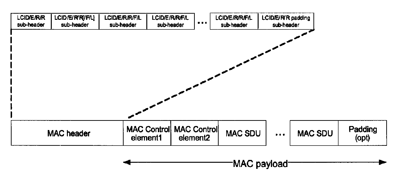
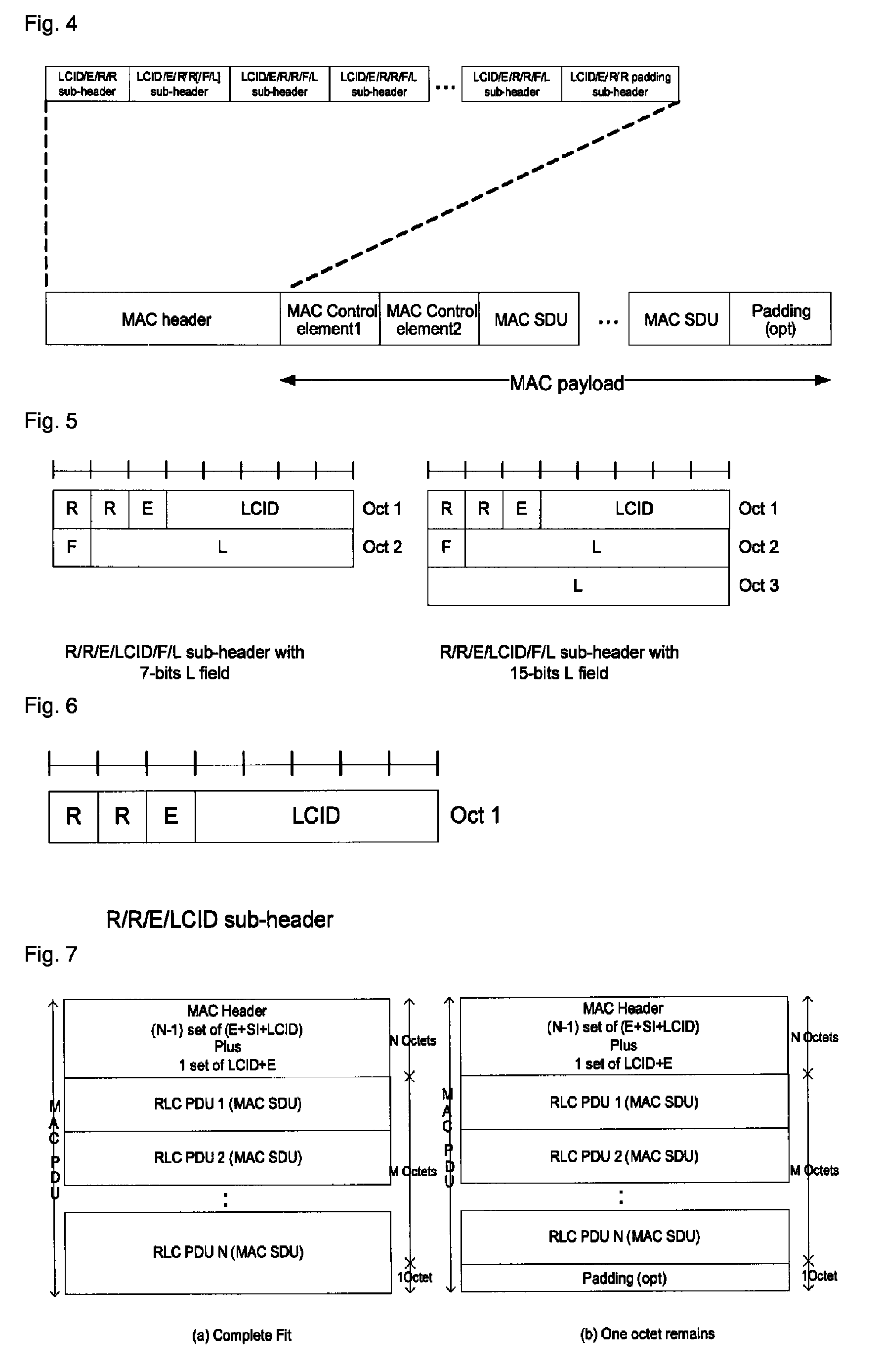
In addition, if an additional header is added to indicate the existence of padding in the last of the MAC PDU in FIG. 7, a problem shown in FIG. 8 would occur.
That is, according to the related art, if there is 1-byte or 2-byte space in the MAC PDU, a problem in generating the MAC PDU would occur.

Method used


Image

  • Effective data block transmission method using header indicator
  • Effective data block transmission method using header indicator
  • Effective data block transmission method using header indicator

Examples


first embodiment

[0037]FIG. 9 shows a method of generating a MAC PDU according to the present invention. In FIG. 9, the R field of MAC sub-header is omitted. FIG. 9(a) is a case when padding is not included in the MAC PDU, and FIG. 9(b) is a case when 1-byte padding is included. In FIG. 9(a), a first PE field is set to 0, indicating that the next field is not the PE field, and accordingly, the padding byte is not included in the MAC PDU. Conversely, in FIG. 9(b), a first PE field is set to 1, indicating that the next field is the PE field. And, a second PE field is set to 0, indicating that the second PE field is the last PE field of the MAC PDU, to thusly indicate that a third PE field is not included in the MAC PDU. Therefore, 1-byte padding exists in the MAC PDU in FIG. 9(b).

[0038]During such process, the MAC header padding used for byte alignment of the MAC header is not considered as the padding. In addition, during the above process, if a total size of the MAC sub-header and a total size of a ...

second embodiment

[0040]FIG. 10 shows a method of generating a MAC PDU according to the present invention. Referring to FIG. 10, the PI is included as the last field of a MAC header, and a value of the PI indicates the number of padding bytes included in the last of the MAC PDU. In FIG. 10(a), if the PI is set to 0, 0 byte padding is present in the MAC PDU. In FIG. 10(b), if the PI is set to 1, 1 byte padding is present in the MAC PDU. In addition, in FIG. 10(c), if the PI is set to 2, 2 byte padding is present in the MAC PDU. Even though the 2-bit PI has been assumed in FIG. 10, 1-bit PI may also be used. In this case, the 1-bit PI may indicate whether or not the 1 byte padding exists or simply indicate whether or not the padding exists.

[0041]Another scheme according to the present invention will be described. Referring to FIGS. 11 and 12, one of the R fields existing in each MAC sub-header is used to indicate an existence of 1 byte padding in the last portion of the MAC PDU. In FIG. 11, the P field...


PUM


Abstract

Disclosed is a radio (wireless) communication system providing a radio communication service and a terminal, and more particularly, to a method of exchanging a data block or data unit between a base station and a terminal in an Evolved Universal Mobile Telecommunications System (E-UMTS) that has evolved from a Universal Mobile Telecommunications System (UMTS) or a Long Term Evolution (LTE) system, which can generate a data block to enhance efficiency of radio resources.

Description

[0001]This application is a 35 U.S.C. §371 National Stage entry of International Application No. PCT / KR2008 / 005497, filed on Sep. 18, 2008, and claims priority to U.S. Provisional Patent Application No. 60 / 973,442, filed Sep. 18, 2007, U.S. Provisional Patent Application No. 60 / 982,710, filed Oct. 25, 2007, and Korean Application No. 10-2008-0091287, filed on Sep. 17, 2008, each of which is hereby incorporated by reference in its entirety as if fully set forth herein.TECHNICAL FIELD[0002]The present invention relates to a radio (wireless) communication system providing a radio communication service and a terminal, and more particularly, to a method of exchanging a data block or data unit between a base station and a terminal in an Evolved Universal Mobile Telecommunications System (E-UMTS) that has evolved from a Universal Mobile Telecommunications System (UMTS) or a Long Term Evolution (LTE) system, which can generate a data block to enhance efficiency of radio resources.BACKGROUND...

Claims


Application Information

Patent Timeline
Patent Type & Authority Patents(United States)
IPC IPC(8): H04L12/58
CPCH04L69/321H04L69/22H04L69/32H04W28/06H04J2211/005H04B2201/70724
Inventor CHUN, SUNG-DUCKYI, SEUNG-JUNEPARK, SUNG-JUNLEE, YOUNG-DAE
Owner LG ELECTRONICS INC
Learn More