
Method of locating the position of a microcalcification in a human breast

a microcalcification and human breast technology, applied in the field of detection and location of microcalcifications in the human breast, can solve the problems of inaccessibility, poor contrast of mammogram images, and high cost of mri,

Inactive Publication Date: 2014-01-07
QUANTASON
View PDF2 Cites 22 Cited by
  • Summary
  • Abstract
  • Description
  • Claims
  • Application Information

AI Technical Summary

Benefits of technology

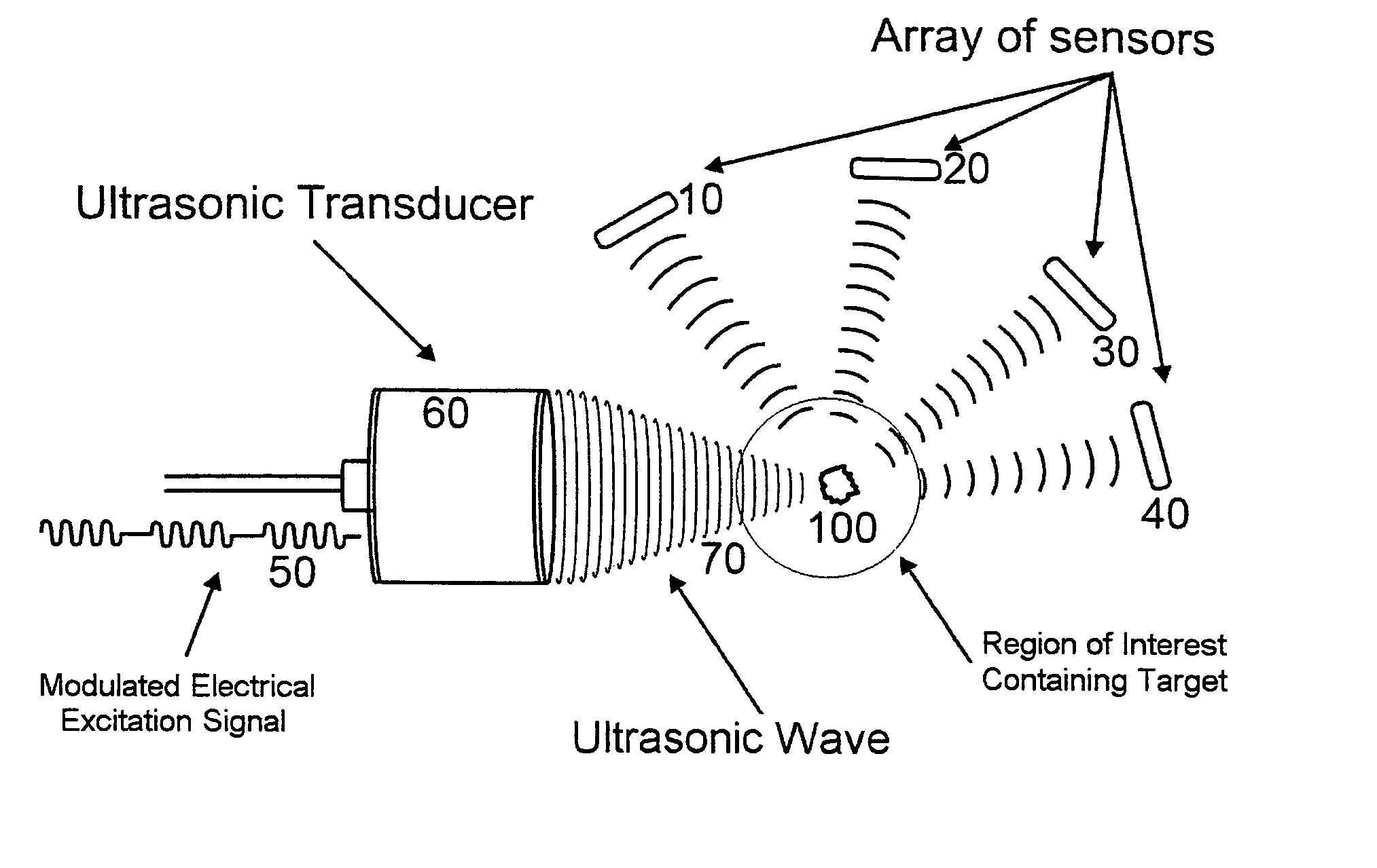
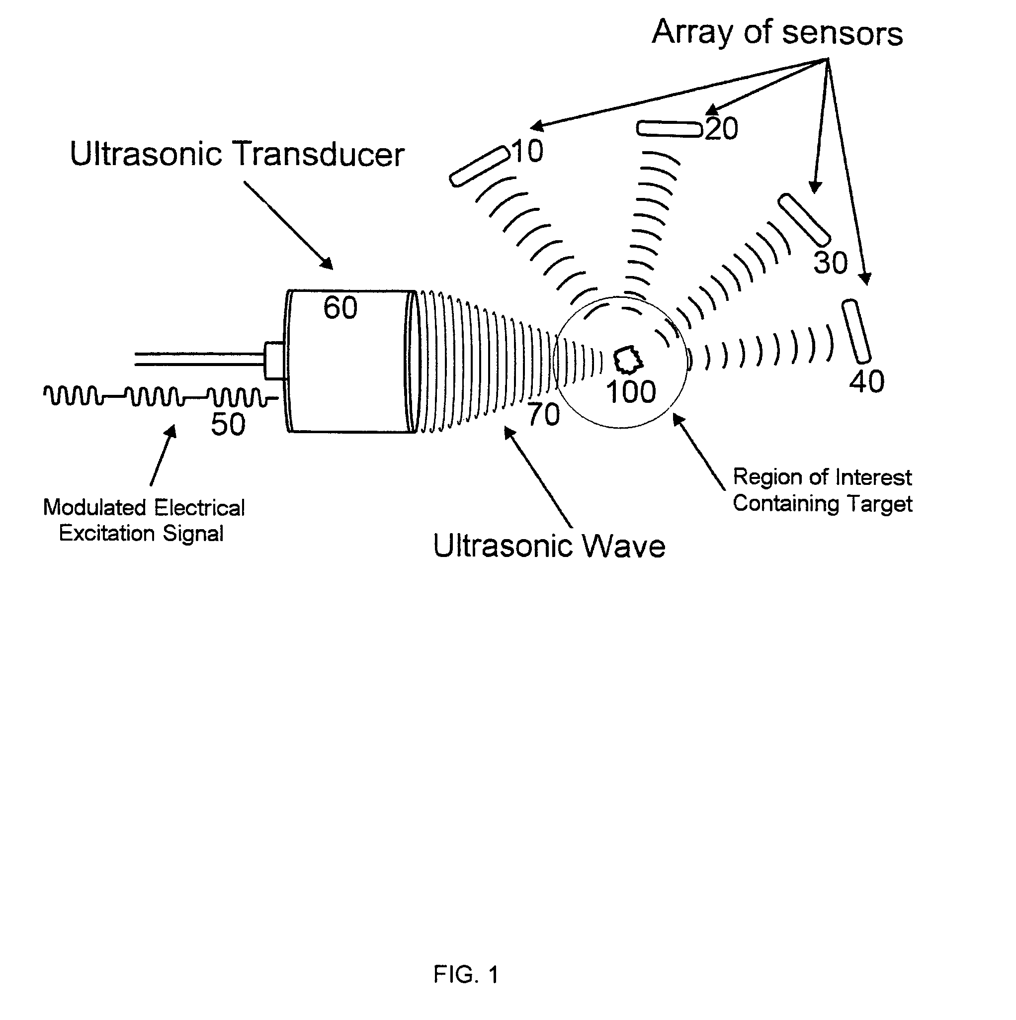
This patent is about a method for accurately locating targets in the body using ultrasound-stimulated detection and location. The method involves analyzing the emitted acoustic signals and using a regression analysis to estimate the phase of the signals. These phase estimates are then converted into a position estimate using a cost function. The method can be used to diagnostic and screen for medical conditions such as microcalcification in breast tissue. The invention also describes a maximum likelihood approach and a method for optimizing the position of the sensors. Overall, the invention provides a more reliable and accurate way to locate targets in the body using ultrasound technology.

Problems solved by technology

Fibroglandular tissue, which is normal in breasts, also appears as white which leads to poor contrast in mammogram images.
Second, a mammogram is an extremely uncomfortable procedure.
Third, mammography is an X-ray based modality which involves exposure to potentially harmful ionizing radiation.
However, MRI is prohibitively expensive and could be out of reach for all but limited number of patients with certain socioeconomic standing.
Moreover, in cases with dense breasts, mammograms have proven useless and thus, ultrasound is the only method of choice, next to expensive and unaffordable MRI.

Method used


Image

  • Method of locating the position of a microcalcification in a human breast
  • Method of locating the position of a microcalcification in a human breast
  • Method of locating the position of a microcalcification in a human breast

Examples


Embodiment Construction

[0030]Although specific embodiments of the presented invention are described herein with reference to the drawings, it should be understood that such embodiments are by way of example only. They merely illustrate but a small number of the many specific embodiments which can represent applications of the principles of the present invention. Various changes and modifications, obvious to one skilled in the art, to which the present invention pertains, are deemed to be within the spirit, scope and contemplation of the present invention as further defined in the appended claims.

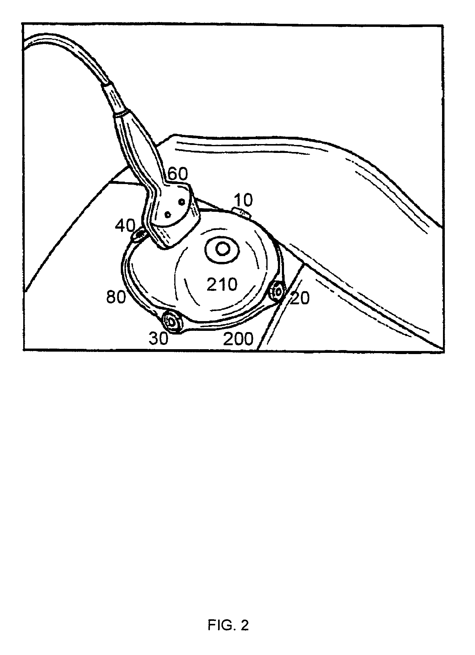
[0031]The initial concept of the present invention is to introduce a multiplicity of acoustic sensors at given locations on or around or adjacent to a human breast. When used in this application, the term “sensor” applies to an acoustic sensor and “acoustic sensor” can include the following: a microphone, microphones, a hydrophone, hydrophones, an accelerometer, accelerometers, a strain gauge, strain gauges, a sur...


PUM


Abstract

This invention relates to diagnostic and screening medical ultrasound in general and to ultrasound-stimulated detection and location, Image-based Dynamic Ultrasound Spectrography, Acoustic Radiation Force Imaging, and similar modalities in particular. In this invention, an ultrasound signal is emitted into tissue and the resulting radiation force induces localized lower frequency oscillations, which are then received by various acoustic sensors and analyzed to determine certain features or characteristics of the interrogated region. The sensors can be arranged in the form of a ring, in any random arrangements, or positioned in specifically chosen locations. An ultrasonic imaging and excitation transducer generates certain stimulating signals which are received by the breast tissues and which, if they contact a microcalcification, other target, or any region with sharply different mechanical and visco-elastic properties, will result in reflected, demodulated, or re-radiated signals. These signals will propagate away from the targets and detected by the various receiving sensors.

Description

BACKGROUND OF THE INVENTION[0001]1. Field of the Invention[0002]The present invention relates to the detection and location of microcalcifications in the human breast with a view to detecting and treating malignant cancer at an early stage.[0003]2. Description of Prior Art[0004]Breast cancer is often characterized by the presence of calcifications along mammary ducts. These may be detected using X-ray mammography. Mammograms do have a number of drawbacks. First, calcifications appear as white objects. Fibroglandular tissue, which is normal in breasts, also appears as white which leads to poor contrast in mammogram images. Second, a mammogram is an extremely uncomfortable procedure. Third, mammography is an X-ray based modality which involves exposure to potentially harmful ionizing radiation. An alternative approach, which does lead to better image quality and diagnosis, is to use magnetic resonance imaging (MRI). However, MRI is prohibitively expensive and could be out of reach for...

Claims


Application Information

Patent Timeline
IPC IPC(8): A61B8/00
CPCG01S15/899G01S15/74A61B8/085A61B8/0825A61B8/485A61B8/5223G01S7/52022G01S7/52036A61B8/4477G01S15/46A61B8/00G06F19/34G01S7/52
Inventor O'RUANAIDH, JOSEPH J.VECCHIO, CHRISTOPHER J.RAMBOD, EDMOND
Owner QUANTASON
Learn More