
In-situ evaluation of reservoir sanding and fines migration and related completion, lift and surface facilities design

a technology of insitu evaluation and reservoir sanding, which is applied in the direction of survey, borehole/well accessories, construction, etc., can solve the problems of inability to restore the stress state of the reservoir to the same level as it was in the reservoir, and the design of the completion of the producing well is a complex process

Inactive Publication Date: 2014-01-07
SCHLUMBERGER TECH CORP
View PDF13 Cites 24 Cited by
  • Summary
  • Abstract
  • Description
  • Claims
  • Application Information

AI Technical Summary

Benefits of technology

Enables real-time, accurate monitoring of sand production and distribution, improving well completion and surface facility design by providing reliable data on sanding potential, reducing sand-related issues and enhancing production efficiency.

Problems solved by technology

The design of the completion of a producing well is a complex process that uses multiple sources of reservoir information.
A common problem for many wells is the tendency to produce solid particles from the reservoir formation, such as sand grains, fine particles, and the like.
However, once a core is extracted from underground, it is impossible to restore it to exactly the same stress state as existed in the reservoir.
Although techniques exist for in-situ measurement of rock properties, these are limited mainly to measuring stress conditions.
However, this test requires sand to be produced to the surface, where all monitoring takes place.
There is no guarantee that all the sand produced by the reservoir will flow to the surface.
In fact, in most cases some portion of the produced sand flowing from the reservoir falls back into the well before it reaches the surface, making the test results unreliable.
In addition, because all monitoring is at the surface (which is many thousands of feet away from the reservoir), there is a lengthy and unquantifiable time delay between what happens downhole and what is monitored at the surface.
Furthermore, since all the control is performed at the surface, the range of flow rates and pressure drawdowns is limited.
There are currently no methods for in-situ measurement of rock material properties such as grain sorting, shape, and size distribution, or measurement of the sanding potential of a reservoir formation.

Method used


Image

  • In-situ evaluation of reservoir sanding and fines migration and related completion, lift and surface facilities design
  • In-situ evaluation of reservoir sanding and fines migration and related completion, lift and surface facilities design
  • In-situ evaluation of reservoir sanding and fines migration and related completion, lift and surface facilities design

Examples


Embodiment Construction

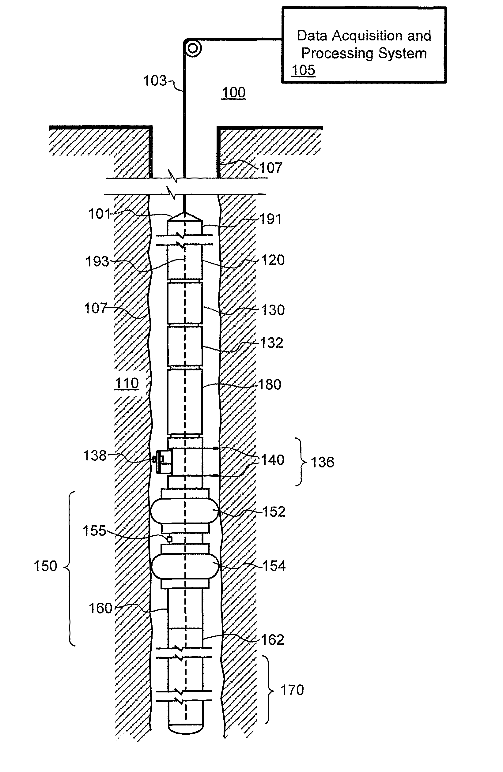
[0019]The particulars shown herein are by way of example and for purposes of illustrative discussion of the embodiments of the present invention only and are presented in the cause of providing what is believed to be the most useful and readily understood description of the principles and conceptual aspects of the present invention. In this regard, no attempt is made to show structural details of the present invention in more detail than is necessary for the fundamental understanding of the present invention, the description taken with the drawings making apparent to those skilled in the art how the several forms of the present invention may be embodied in practice. Further, like reference numbers and designations in the various drawings indicated like elements.

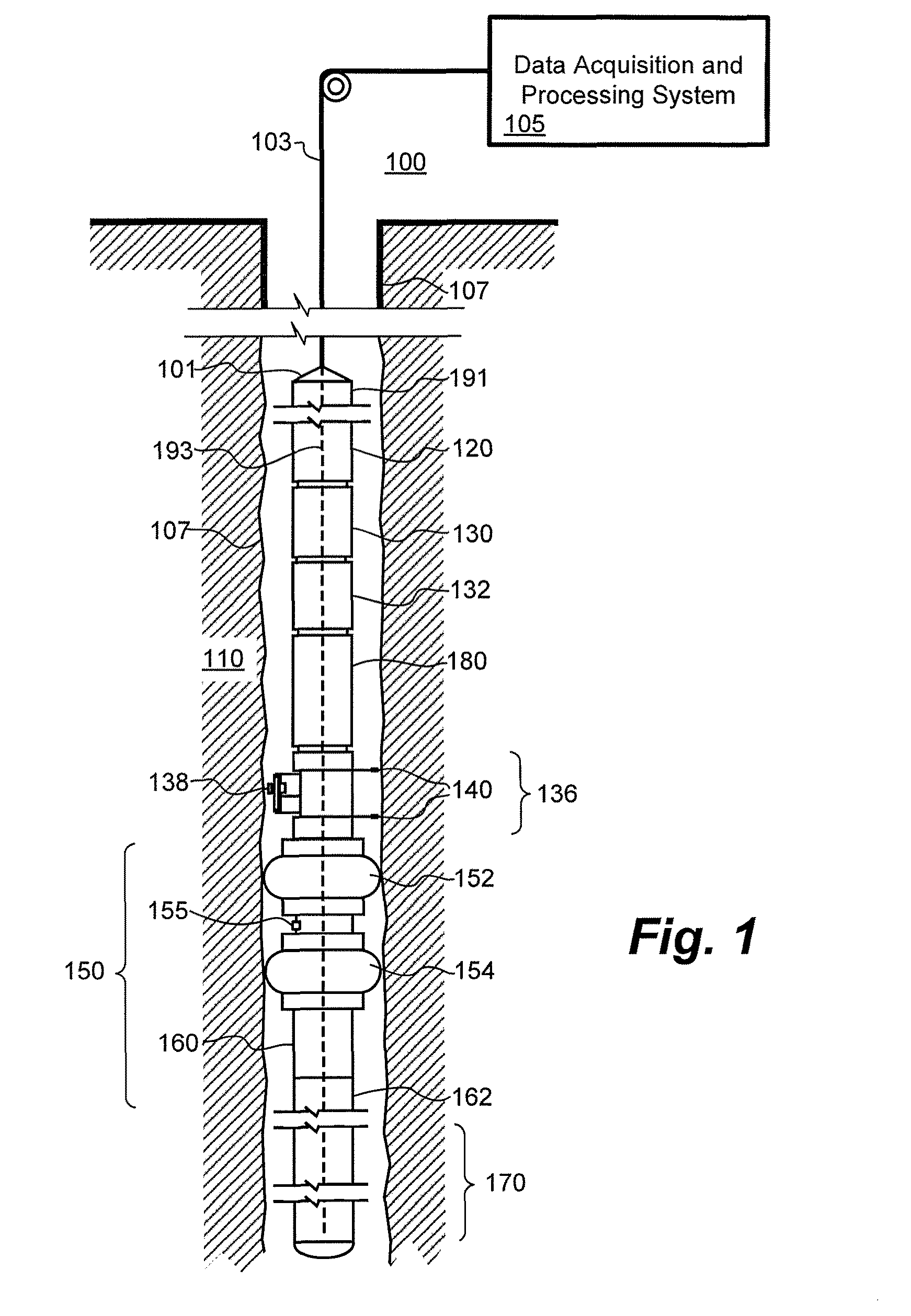
[0020]This patent specification generally relates to the field of downhole fluid analysis and in-situ formation evaluation. According to some embodiments, these activities are practiced during a formation test. According to s...


PUM


Abstract

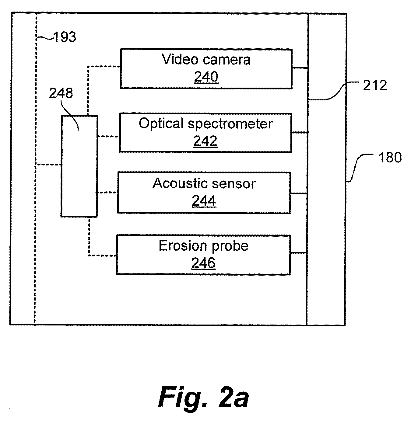
Methods and related systems are described relating to monitoring particulates downhole at in-situ conditions. Solid particles being carried in the fluid as the fluid is produced from the reservoir formation are monitored. The downhole solid particle monitoring can include measuring the quantity (e.g., volume fraction, weight fraction, or the like) of solid particles, measuring the distribution of sizes of the solid particles, and / or measuring the shape of the particles. The solid particles can be monitored using one or more of sensors such as optical spectrometers, acoustic sensors, video cameras, and erosion probes. A sanding prediction is generated based at least in part on the monitoring of the solid particles, and the sanding prediction is then used to design a completion, lift system, and surface facilities for the wellbore and / or select operating conditions so as to control sanding during production.

Description

CROSS-REFERENCE TO RELATED APPLICATIONS[0001]This patent application claims benefit of Provisional Patent Application Ser. No. 61 / 168,222 filed on Apr. 10, 2009, which is incorporated by reference herein.BACKGROUND OF THE INVENTION[0002]1. Field of the Invention[0003]This patent specification generally relates to downhole fluid analysis and in-situ formation evaluation. More particularly, this patent specification relates to in-situ evaluations of reservoir sanding and fines migrations.[0004]2. Background of the Invention[0005]The design of the completion of a producing well is a complex process that uses multiple sources of reservoir information. Similarly, the design of the production system, including artificial lift and surface facilities, relies on such information. A common problem for many wells is the tendency to produce solid particles from the reservoir formation, such as sand grains, fine particles, and the like. The production of solid particles is usually termed “sandin...

Claims


Application Information

Patent Timeline
Patent Type & Authority Patents(United States)
IPC IPC(8): E21B47/00
CPCE21B49/08E21B47/10E21B49/10E21B47/101E21B2049/085E21B47/107E21B49/0875E21B49/088
Inventor HEGEMAN, PETER, S
Owner SCHLUMBERGER TECH CORP
Learn More