
Moldable cushion for implants

a cushion and implant technology, applied in the field of implants, can solve the problems of patients' discomfort at the bone-implant interface, limited ability of metal implants to match the contour of the underlying bone, and often the site of step-off, so as to facilitate and secure seat the cushion, reduce friction between the surfaces, and minimize discomfort and the risk of irritation, injury or infection

Active Publication Date: 2013-12-31
HIGHTOWER CHARLES D
View PDF42 Cites 0 Cited by
  • Summary
  • Abstract
  • Description
  • Claims
  • Application Information

AI Technical Summary

Benefits of technology

The present invention is about providing medical implant cushions made of a special polymer that can be easily shaped and secured onto the implant during surgery. These cushions help to minimize discomfort, risk of irritation, injury, or infection caused by a prominent bone-implant step-off. The polymer used in the cushion is lubricious and mildly visco-elastic, which helps to absorb contact stress by deforming under applied pressure and then regaining its shape as the pressure is removed. The cushion can be easily removable from the implant and includes radio-opaque strips or other identification codes for patient safety.

Problems solved by technology

Despite new advances in low profile implant technologies, metal implants are limited in their ability to match the contour of the underlying bone.
The result is often a step-off at the bone-implant interface.
The existence of such a step-off can cause a variety of issues.
Such a step-off is often the site of discomfort for patients, particularly when skin, muscle, or other tissues are pushed against the step-off.
In addition, the surfaces of metal implants are a source of friction between such implants and surrounding soft tissues which are constantly moving.
Problems arising from such friction are most extreme when a tendon is overlying the implant.
Such friction can not only cause painful tendonitis, but can also eventually lead to a rupture of the tendon.
Whether used alone or to fasten another orthopedic implant in place, the screws are often prominent and painful.
The result is often painful irritation.
In extreme cases, the implanted hardware can erode through the skin causing dangerous ulceration requiring prolonged wound care and increased risk of infection.
Dental and maxillofacial implants used to treat or repair bones of the jaw and face and similar implants used in plastic surgery often result in a step-off at the bone-implant interface or in friction between the implant and soft tissue covering the implant.
Such a step-off or friction can lead to substantial discomfort and in severe cases ulceration, infection, and damage to the surrounding tissue.
Neither of these two approaches have successfully or universally solved the significant problems which exist.
The significant limitations of these two approaches becomes apparent after a surgeon modifies the plate shape to fit the affected bone.
Failing to properly modify the shape of the plate to fit the bone can cause poor fracture healing if the bone fragments are not properly opposed.
Also, once the shape of the plate has been modified, preformed plastic covers often no longer fit the implant.
The application of a preformed plastic cover after the surgeon modifies the shape of the plate so the bone fragments are properly opposed is often not possible or the result is an unacceptably loose, insecure fit between the plate and the cover.
While such covers can be designed to fit a plate of a particular shape and reduce the step-off, any change in the shape of the plate can result in the cover exacerbating rather than reducing this step-off.
For a variety of reasons, such materials have rarely, if ever, been used to reduce friction between an implant and surrounding tissue or a step-off at the bone-implant interface.
These materials have not been employed to either reduce friction or to reduce a bone-implant step-off.
The use of a bio-absorbable material would likely only temporarily reduce friction.
Also, generation of tissue around an implant could make explantation more difficult and give rise to a number of other anatomical issues making the use of such materials undesirable.

Method used


Image

  • Moldable cushion for implants
  • Moldable cushion for implants
  • Moldable cushion for implants

Examples


Embodiment Construction

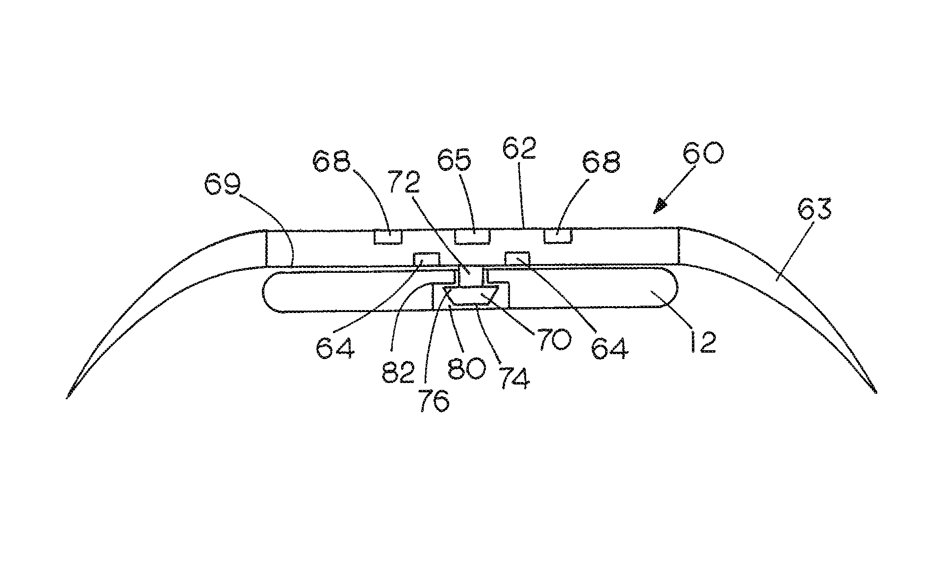
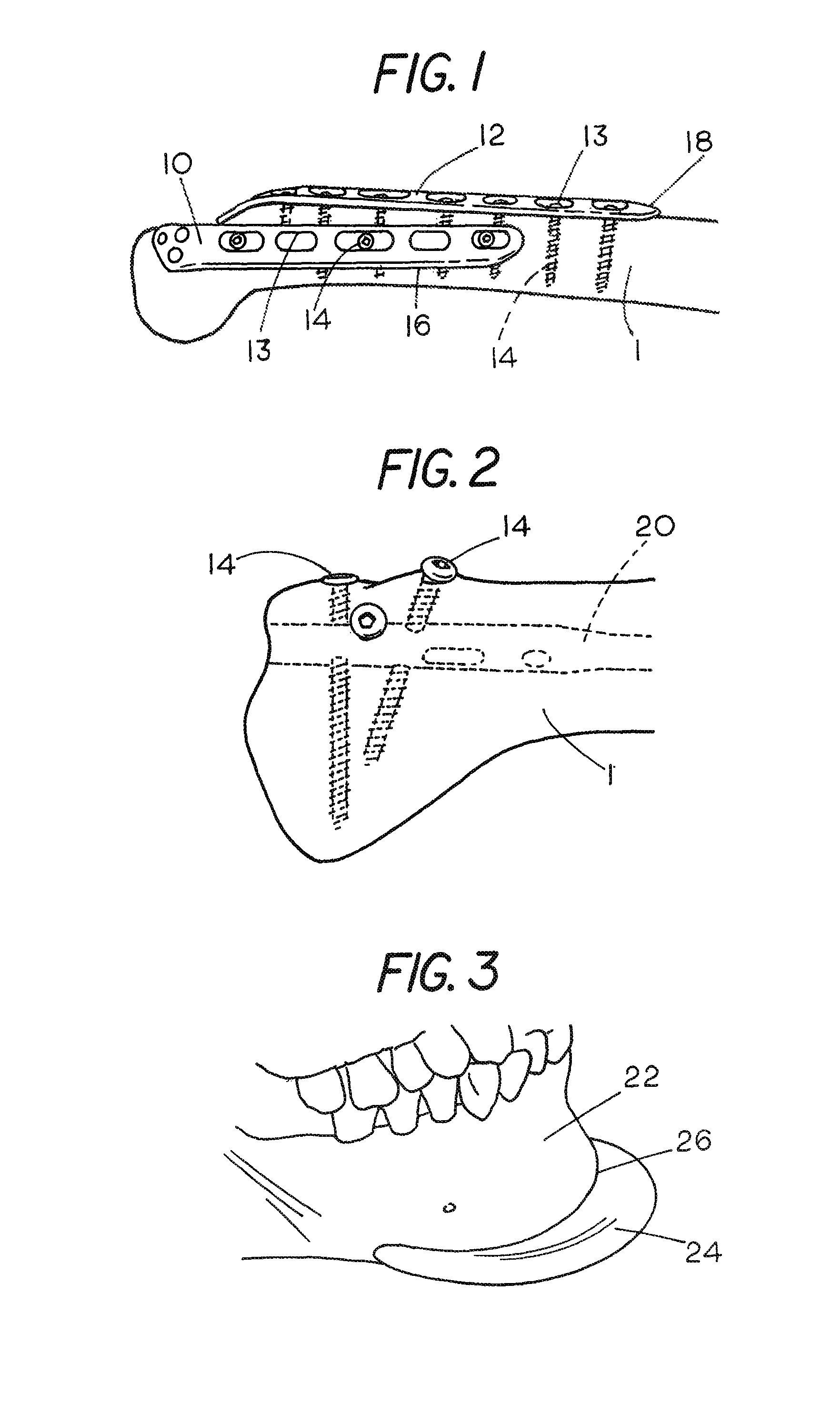
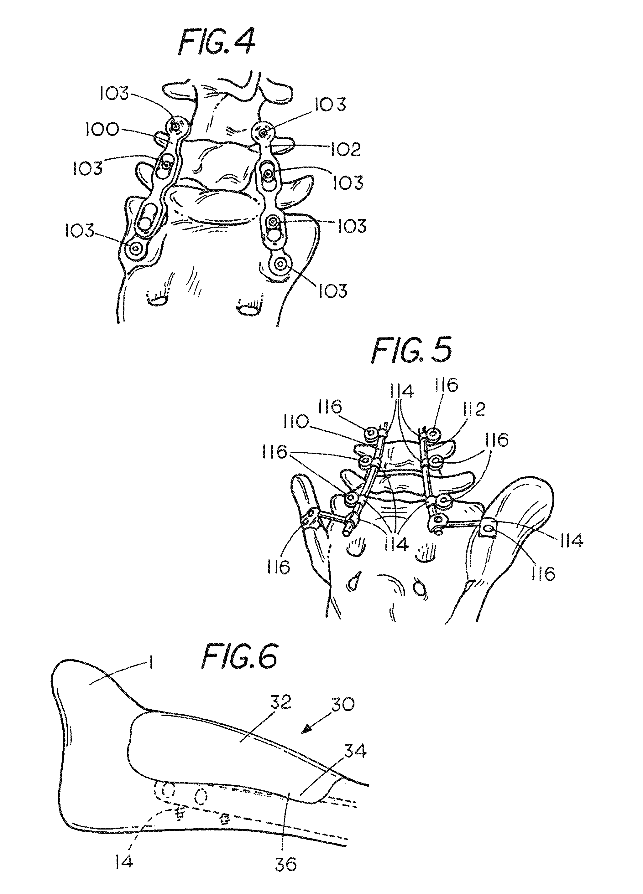
[0032]FIGS. 1-5 show representative examples of the types of implants employed by surgeons today. FIG. 1 shows a bone 1 which has been fractured and a pair of orthopedic implant plates 10 and 12 employed for fixation of the fracture. Each plate has a plurality of holes 13 surrounded by a recessed flange. The plates are made of a suitable metal such as titanium. Screws 14 are used to fasten the plates 10 and 12 to the bone 1. The screws 14 include a threaded shaft having a diameter smaller than the hole 13 and a head which engages the recessed flange surrounding the hole 13 to fix the plate 10 or 12 to the bone 1. The bone-implant step-off associated with plate 10 is shown at 16. The bone-implant step-off associated with plate 12 is shown at 18. As shown, the shape of each of plates 10 and 12 has been modified to match the contours of the bone 1 and provide a proper alignment between the bone fragments on opposite sides of the fracture.

[0033]FIG. 2 shows a rod 20 which has been place...


PUM


Abstract

Custom moldable cushions for covering medical implants fastened to a bone are provided. Such cushions inhibit irritation of the surrounding soft tissue by covering the bone-implant interface and by reducing friction caused by movement of soft tissue adjacent the implant. Such cushions may also be employed to spread and absorb forces reducing patient discomfort and risk of injury and infection associated with such implants.

Description

CROSS-REFERENCED TO RELATED APPLICATIONS[0001]Not applicable.STATEMENT REGARDING FEDERALLY SPONSORED RESEARCH OR DEVELOPMENT[0002]Not applicable.BACKGROUND OF THE INVENTION[0003]I. Field of the Invention[0004]The present invention relates to implanted orthopedic, maxillofacial, spinal and plastic surgery hardware. More specifically, the present invention relates to cushions which cover such hardware to cushion the surrounding tissue from such hardware.[0005]II. Related Art[0006]Orthopedic implants made of various materials are employed to provide adequate strength to resist biologic stress across a pathologic area during bone healing. Orthopedic implants are often made of metal such as titanium which can be forged or bent in a variety of ways to allow such implants to conform to a surface of the bone to some degree while maintaining the mechanical properties of the implant. Despite new advances in low profile implant technologies, metal implants are limited in their ability to match...

Claims


Application Information

Patent Timeline
Patent Type & Authority Patents(United States)
IPC IPC(8): A61F2/02
CPCA61B17/8042A61B17/8028A61F2002/30688A61F2002/3007A61B17/685
Inventor HIGHTOWER, CHARLES, D.
Owner HIGHTOWER CHARLES D
Learn More