
Firefighting monitor and control system therefor

a monitor and control system technology, applied in the field of firefighting monitor and control system therefor, can solve the problems of increasing inventory requirements, increasing the cost to users, and requiring different storage configurations of monitors,

Active Publication Date: 2013-12-10
ELKHART BRASS MFG
View PDF175 Cites 19 Cited by
  • Summary
  • Abstract
  • Description
  • Claims
  • Application Information

AI Technical Summary

Benefits of technology

Enables quick and easy modification of firefighting monitors to suit multiple applications through a centralized system, reducing the need for manual adjustments and inventory, while allowing for firmware updates and customizable settings.

Problems solved by technology

In addition to the different motors and different communication formats, monitors often need different stow configurations and set limits on their range of motion.
This can add to inventory requirements and the cost to the users.

Method used


Image

  • Firefighting monitor and control system therefor
  • Firefighting monitor and control system therefor
  • Firefighting monitor and control system therefor

Examples


Embodiment Construction

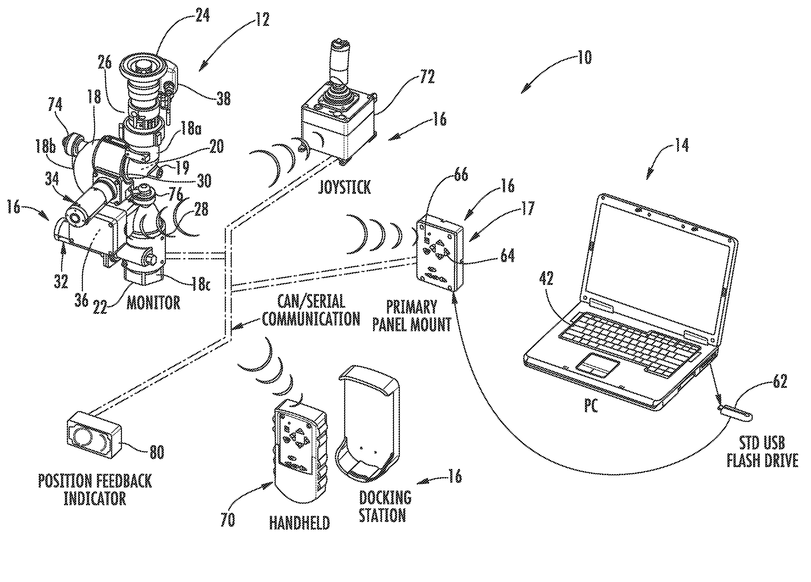
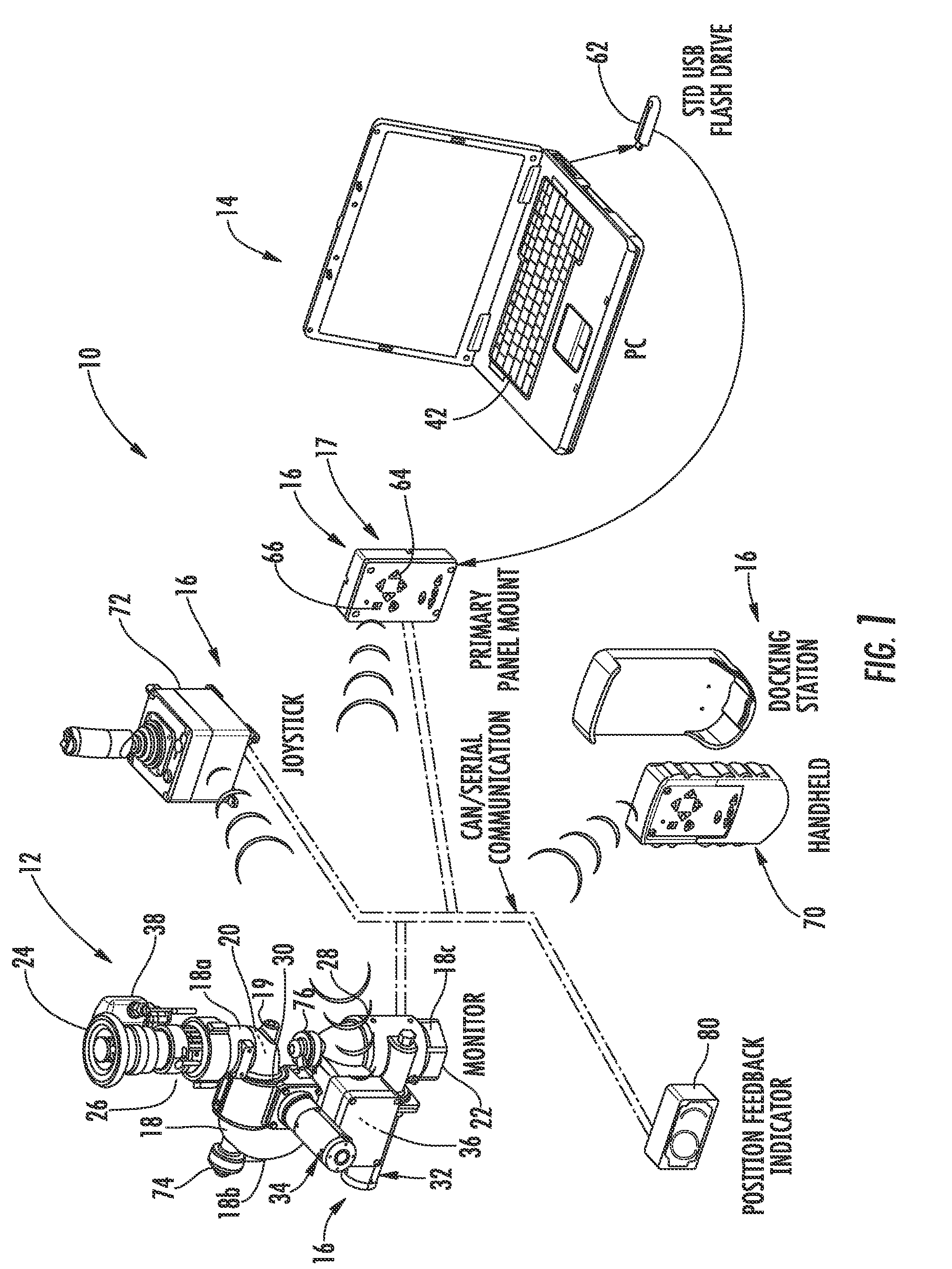
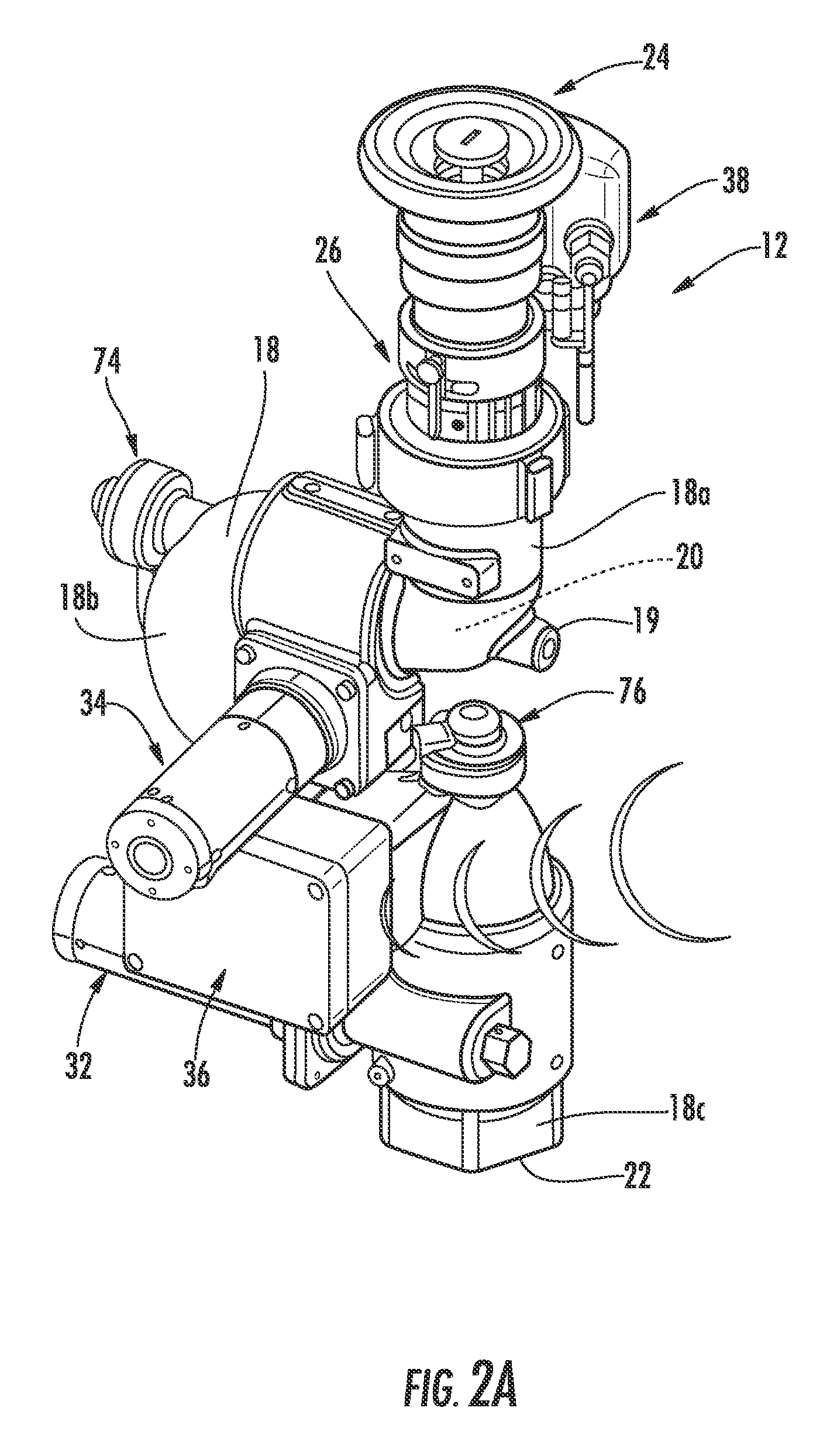
[0024]Referring to FIG. 1, the numeral 10 generally designates a firefighting monitor and control system of the present invention. As will be more fully described below, firefighting monitor and control system 10 includes a monitor 12 and a computer 14, which is configured to allow the parameters of the monitor 12 (and its associated controllers) to be selected and modified based on a user's needs so that the monitor can be customized by the user. As will be more fully described below, computer 14 includes a software program that generates a menu to allow a user to select the different parameters of the monitor and, further, of the monitor's input control devices 16 (e.g. panel mounted control unit 17, monitor based control unit 36, handheld control unit 70, and joystick control unit 72, all described below) to be customized and then modified as needed.

[0025]Although system 10 is illustrated with a single panel mounted control unit 17, monitor based control unit 36, handheld control...


PUM


Abstract

A firefighting monitor system includes a monitor, a controller selectively generating signals to the monitor for controlling the monitor, and a computer. The computer is configured to receive input from a user relative to the monitor or the controller. The computer generates an output based on the input, and the output is transmitted to the controller for controlling the monitor or the controller in accordance with the output.

Description

CROSS-REFERENCE TO RELATED APPLICATIONS[0001]This application claims priority and the benefit of provisional application entitled FIREFIGHTING MONITOR AND CONTROL SYSTEM THEREFOR, Ser. No. 61 / 171,700, filed Apr. 22, 2009, which is incorporated herein by reference in its entirety[0002]The present invention relates to a firefighting monitor and, more particularly, to a firefighting monitor with a control system for controlling various parameters associated with the firefighting monitor.TECHNICAL FIELD AND BACKGROUND OF THE INVENTION[0003]Firefighting monitors are used to control the flow of fluid, such as water, and are typically formed from curved pipe sections that form an outlet (to which a nozzle is mounted) and an inlet that connects to a supply of fluid. The pipe sections are connected together to form a curved fluid passageway and mounted to allow articulation of the pipe sections so that the position of the outlet can be varied.[0004]Monitors may be controlled manually or may ...

Claims


Application Information

Patent Timeline
Patent Type & Authority Patents(United States)
IPC IPC(8): G05B11/01G05B15/00A62C37/00G08B25/00A62C3/00A62C37/10
CPCA62C37/00G05B19/042G05D7/06A62C31/28A62C37/40A62C35/68G05B19/416G05B2219/37371G05D7/0617
Inventor LOZIER, TODD B.TRAPP, JAMES M.JONES, LEE R.COMBS, ERIC N.
Owner ELKHART BRASS MFG
Learn More