
Depositing texture on receiver

a texture and receiver technology, applied in the field of printing, can solve the problems of interrupting the viewer's perception of the texture, high-frequency data that is corrupted by compression, etc., and achieve the effect of high-fidelity textures without increasing the bandwidth requirements of image transmission

Active Publication Date: 2013-12-10
EASTMAN KODAK CO
View PDF12 Cites 1 Cited by
  • Summary
  • Abstract
  • Description
  • Claims
  • Application Information

AI Technical Summary

Benefits of technology

This patent describes a way to make pictures look better without needing more data to send them over the internet. It uses information from the picture to create a texture that matches the picture, making it harder to tamper with or counterfeit. The patent also lets users create their own textures and ensures that pictures can be authenticated based on their unique characteristics.

Problems solved by technology

However, texture data often contains high-frequency data that is corrupted by compression.
Moreover, even if compression restores the texture data, it can introduce block boundaries (e.g., every 8×8 or 16×16 pixels) that interrupt the viewer's perception of the texture.

Method used


Image

  • Depositing texture on receiver
  • Depositing texture on receiver
  • Depositing texture on receiver

Examples


Embodiment Construction

[0023]In the following description, some embodiments will be described in terms that would ordinarily be implemented as software programs. Those skilled in the art will readily recognize that the equivalent of such software can also be constructed in hardware. Because image manipulation algorithms and systems are well known, the present description will be directed in particular to algorithms and systems forming part of, or cooperating more directly with, embodiments described herein. Other aspects of such algorithms and systems, and hardware or software for producing and otherwise processing the image signals involved therewith, not specifically shown or described herein, are selected from such systems, algorithms, components, and elements known in the art. Given the system as described herein, software not specifically shown, suggested, or described herein that is useful for implementation of the invention is conventional and within the ordinary skill in such arts.

[0024]A computer...


PUM


Abstract

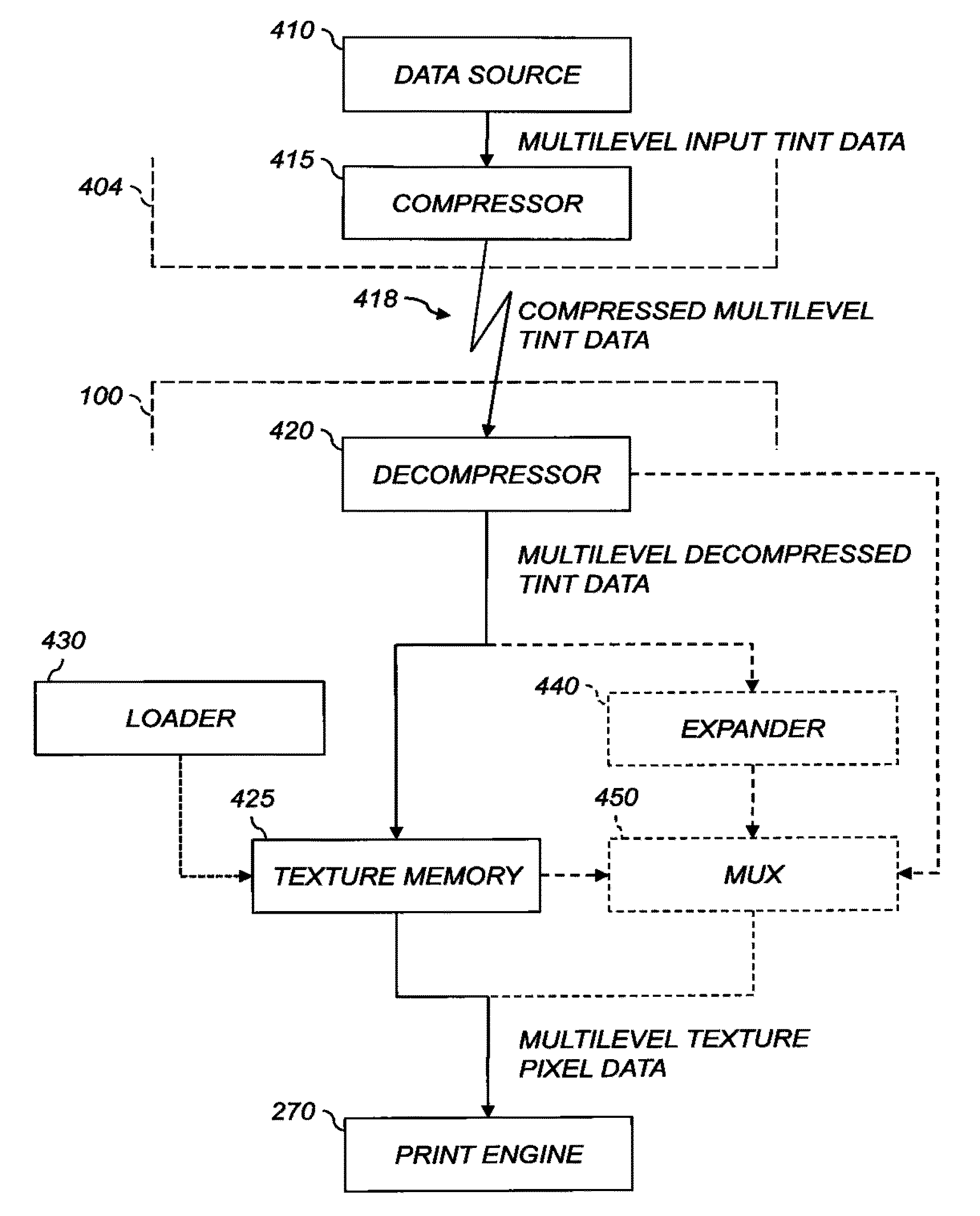
Apparatus for depositing a texture on a receiver includes a data source that provides multilevel input tint data values. A lossy compressor produces compressed multilevel tint data values from the multilevel input tint data values. A decompressor produces multilevel decompressed tint data values from the compressed multilevel tint data values. A texture memory receives those values from the decompressor and provides corresponding multilevel texture pixel data values. A print engine deposits at each of a plurality of pixel sites on the receiver an amount of texture-forming material corresponding to the respective multilevel texture pixel data value. A loader loads into the texture memory a texture set including multilevel texture pixel data values for each of a plurality of textures, and each texture in the texture set corresponds to a respective selected range of multilevel decompressed tint data value.

Description

FIELD OF THE INVENTION[0001]This invention pertains to the field of printing and more particularly to improving image quality of various types of printed images.BACKGROUND OF THE INVENTION[0002]Electrophotographic printers produce images by depositing toner on receivers (or “imaging substrates”), such as pieces or sheets of paper or other planar media, glass, fabric, metal, or other objects. Printers typically operate using subtractive color: a substantially reflective receiver is overcoated image-wise with cyan (C), magenta (M), yellow (Y), black (K), and other colorants. Other toner compositions can be used to produce effects beyond simple image appearance.[0003]For example, U.S. Publication No. 20080159786 by Tombs et al., entitled “Selective printing of raised information by electrography,” published Jul. 3, 2008, the disclosure of which is incorporated herein by reference, describes electrophotographic printing using marking particles of a substantially larger size than the sta...

Claims


Application Information

Patent Timeline
Patent Type & Authority Patents(United States)
IPC IPC(8): H04N1/40
CPCG06K1/121G03G15/5025G03G15/6591G03G15/224
Inventor KUO, CHUNG-HUITAI, HWAI-TZUUHARTMAN, JOHN T
Owner EASTMAN KODAK CO
Learn More