Vehicle power transmission device and control system for power transmission

a power transmission device and power transmission technology, applied in the direction of engine-driven generators, transportation and packaging, transportation, etc., can solve the problems of the efficiency reduction of the use of rotational energy in the power transmission device, and achieve the elimination of the loss of rotational energy, minimizing mechanical vibrations, and eliminating the transmission of torque pulsation

Active Publication Date: 2013-11-26
DENSO CORP
View PDF17 Cites 8 Cited by
  • Summary
  • Abstract
  • Description
  • Claims
  • Application Information

AI Technical Summary

Benefits of technology

[0010]Specifically, the signs of power of the second and third rotors of the second rotor set are different from each other, thus enabling the sign of the speed of the first rotor of the second rotor set to be reversed even when the signs of speeds of the second and third rotors of the second rotor set remain unchanged. This permits the sign of power of the second rotor of the first rotor set to be reversed by reversing the sign of power of the first rotor of the second rotor set, thereby enabling a condition in which the signs of power of the second and third rotor of the first rotor set are identical with each other to be switched to a condition in which the signs of power of the second and third rotor of the first rotor set are different from each other, in other words, a power circulation mode in which the power is circulated between the second and third rotors of the first rotor set to be changed to a non power circulation mode in which the power is not circulated between the second and third rotors of the first rotor set.
[0028]According to the second aspect of the invention, there is provided a power transmission control system for a vehicle which comprises: (a) a first rotor set including a first, a second, and a third rotor which are so linked mechanically as to have rotational speeds thereof arrayed on a straight line in a nomographic chart; (b) a second rotor set including a first, a second, and a third rotor which are so linked mechanically as to have rotational speeds thereof arrayed on a straight line in a nomographic chart; (c) a first and a second switching mechanism; and (d) a controller. The first and second rotor sets work as a power split device to transmit rotational energy, as produced by a power source, to a driven wheel of a vehicle. The first rotor of the first rotor set is connected mechanically to the driven wheel. The second rotor of the first rotor set is connected mechanically to the first rotor of the second rotor set. The second and third rotors of the second rotor set are so linked as to have signs of power which are different from each other. The first switching mechanism is placed selectively in one of an engaged state establishing a mechanical connection between the second rotor of the first rotor set and the first rotor of the second rotor set and a disengaged state blocking the mechanical connection between the second rotor of the first rotor set and the first rotor of the second rotor set. The second switching mechanism is placed selectively in one of an engaged state establishing a mechanical connection between the second rotor of the first rotor set and the second rotor of the second rotor set and a disengaged state blocking the mechanical connection between the second rotor of the first rotor set and the second rotor of the second rotor set. The controller places both the first and second switching mechanisms in the disengaged states thereof when a travel permission switch for the vehicle is in an off-state. This avoids undesirable rotation of the speed variator when the vehicle is towed.

Problems solved by technology

However, such a condition will result in circulation of power between the two of the rotors, thus resulting in a decrease in efficiency of use of rotational energy in the power transmission device.

Method used


Image

  • Vehicle power transmission device and control system for power transmission
  • Vehicle power transmission device and control system for power transmission
  • Vehicle power transmission device and control system for power transmission

Examples


Embodiment Construction

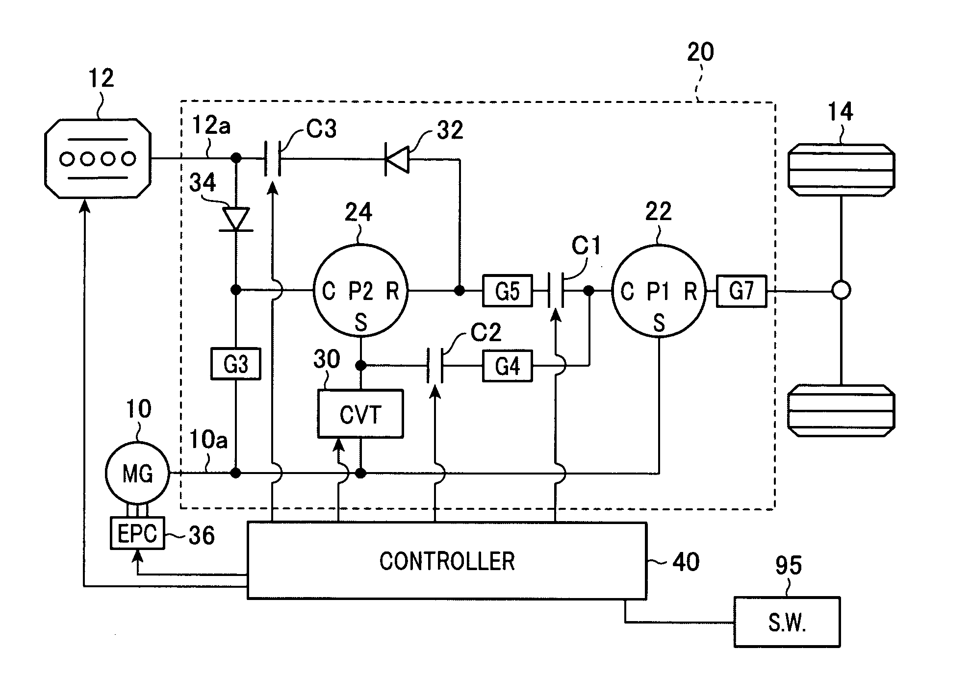
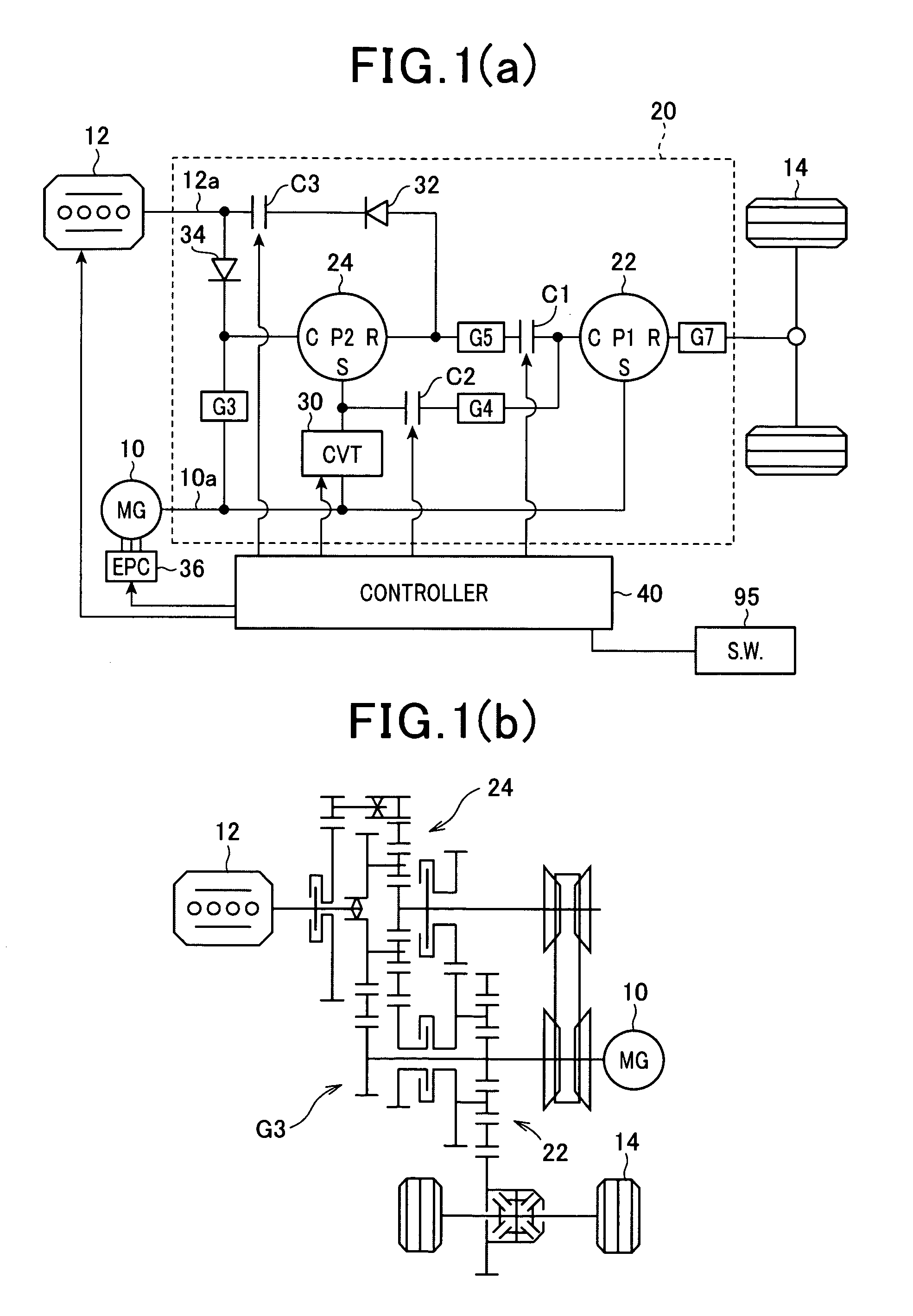
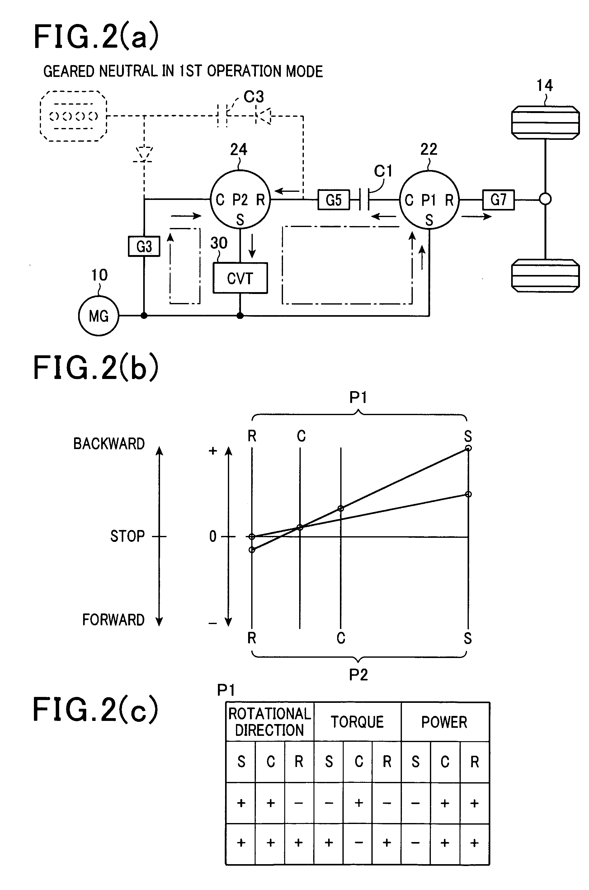
[0062]Referring to the drawings, wherein like reference numbers refer to like parts in several views, particularly to FIGS. 1(a) and 1(b), there is shown a hybrid system equipped with a power transmission control system according to the first embodiment of the invention. The power transmission control system is equipped with a power transmission device and a controller working to control an operation of the power transmission device.

[0063]FIG. 1(a) illustrates the structure of the hybrid system. FIG. 1(b) is a skeleton view of power transmission paths.

[0064]The hybrid system includes a motor-generator 10, an internal combustion engine 12 (e.g., a gasoline engine), and a power transmission device 20. The motor-generator 10 is made of a three-phase ac motor-generator and works as an in-vehicle power producing device along with the internal combustion engine 12 to run an automotive vehicle. The power transmission device 20 is equipped with first planetary gear set 22 and a second plane...


PUM


Abstract

A power transmission apparatus for a vehicle which includes a first and a second planetary gear set to transmit power to a driven wheel. A ring gear of the first planetary gear set is coupled to the driven wheel. A carrier of the first planetary gear set is coupled to a ring gear of the second planetary gear set. A carrier and a sun gear of the second planetary gear set are so linked as to have signs of power which are opposite each other. A sign of speed of the ring gear of the second planetary gear set is reversed under the condition that the a sign of speed of a motor-generator is fixed, thereby reversing the sign of speed of the carrier of the first planetary gear set, which eliminate the circulation of power between the sun gear and the carrier of the first planetary gear set.

Description

CROSS REFERENCE TO RELATED DOCUMENT[0001]The present application claims the benefits of Japanese Patent Application No. 2009-261386 filed on Nov. 16, 2009, the disclosure of which is incorporated herein by reference.BACKGROUND OF THE INVENTION[0002]1. Technical Field of the Invention[0003]The present invention relates generally to a power transmission device for a vehicle which is equipped with a plurality of power split rotors which work to split an output power or torque between a power source such as an electric rotating machine (e.g., a dynamo-electric machine) or an internal combustion engine and a driven wheel of the vehicle and are designed to rotate in conjunction with each other and a power transmission control system for such a power transmission device.[0004]2. Background Art[0005]Japanese Patent First Publication No. 2006-308039 discloses a power transmission device to be installed in an automotive vehicle. The power transmission device is equipped with a first and a sec...

Claims


Application Information

Patent Timeline
Patent Type & Authority Patents(United States)
IPC IPC(8): F16H3/72F16H37/06F16H37/02B60K6/36B60K6/365B60K6/38B60K6/48B60K6/543B60L50/16B60W10/02B60W10/10B60W20/00F16H59/02F16H61/02F16H61/662F16H61/664F16H63/50
CPCB60K6/48F16H37/0846B60K6/543B60K2006/4816F16H61/702F16H2037/101F16H2061/6601F16H2200/2007Y02T10/6221Y02T10/6256F16H2200/2084F16H2200/2035Y02T10/62
Inventor KAWASAKI, KOJIMATSUE, TAKENORI
Owner DENSO CORP
Why Eureka
Try Eureka