Caster wheel assembly for a snowblower

a technology of caster wheels and snowblowers, applied in the field of snowblowers, can solve problems such as inability to summarize, and achieve the effect of convenient maneuverability and easy movement over the surfa

Active Publication Date: 2013-11-19
SPERRY CAROL F +1
View PDF18 Cites 20 Cited by
  • Summary
  • Abstract
  • Description
  • Claims
  • Application Information

AI Technical Summary

Benefits of technology

The invention provides a snowblower with caster wheels that make it easier to move and maneuver over snow surfaces. This improves the efficiency and effectiveness of snow removal.

Problems solved by technology

Moreover, this Summary is not intended for use as an aid in determining the scope of the claimed subject matter.

Method used


Image

  • Caster wheel assembly for a snowblower
  • Caster wheel assembly for a snowblower
  • Caster wheel assembly for a snowblower

Examples


Embodiment Construction

[0019]Embodiments are described more fully below with reference to the accompanying figures, which form a part hereof and show, by way of illustration, specific exemplary embodiments. These embodiments are disclosed in sufficient detail to enable those skilled in the art to practice the invention. However. embodiments may be implemented in many different forms and should not be construed as being limited to the embodiments set forth herein. The following detailed description is, therefore, not to be taken in a limiting sense in that the scope of the present invention is defined only by the appended claims.

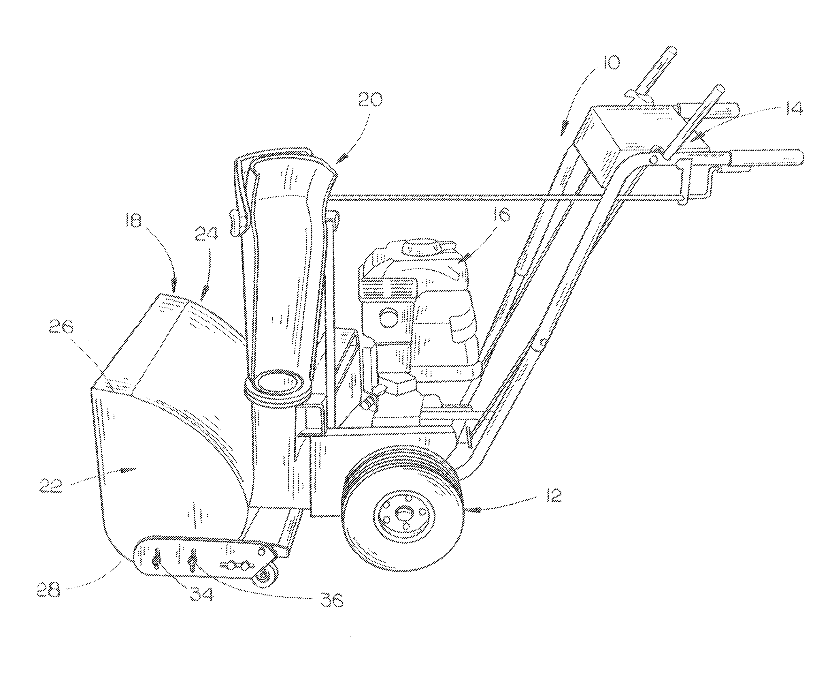
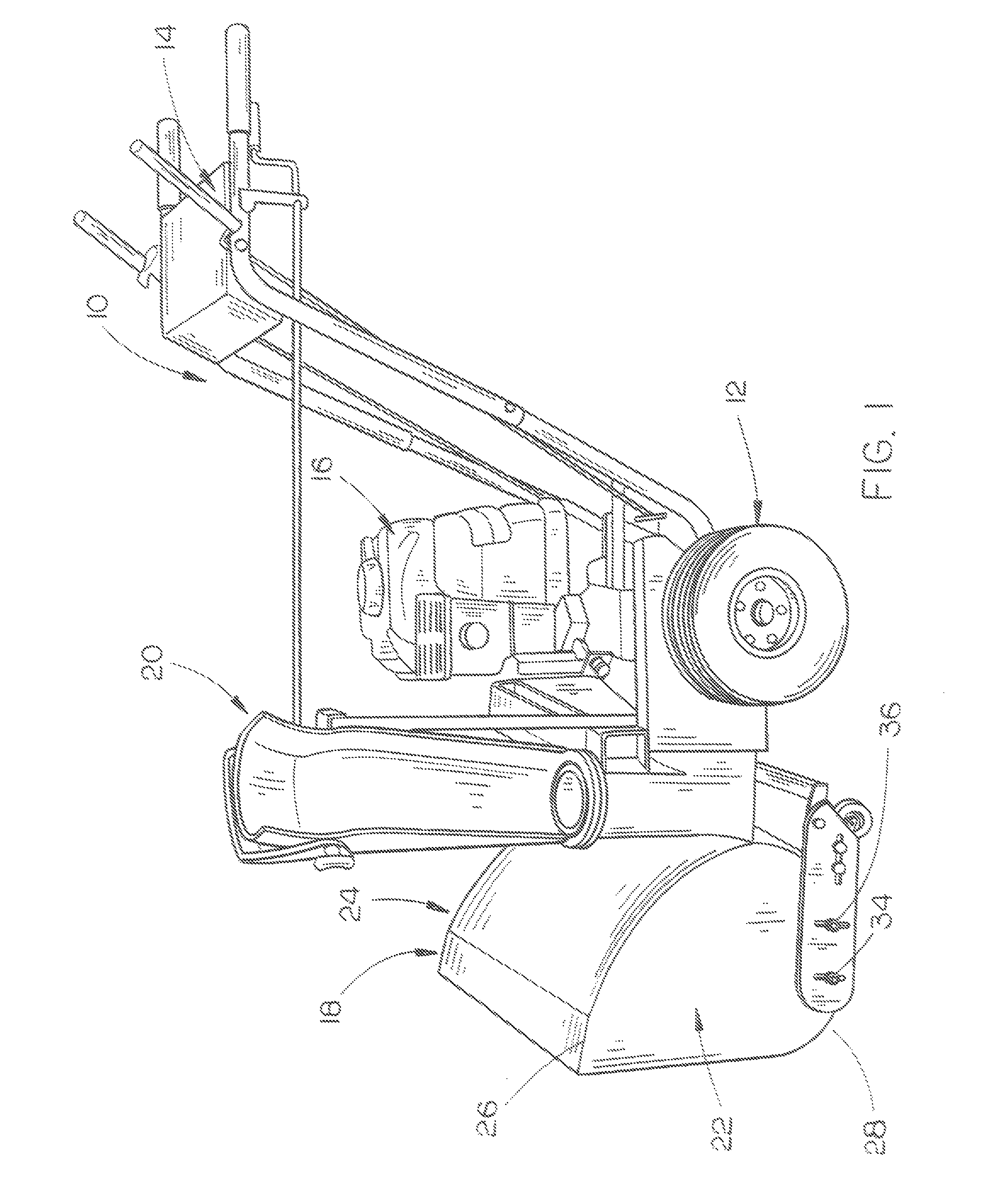
[0020]In FIGS. 1 and 2, the numeral 10 refers to generally to a snowblower of conventional design which includes a wheeled frame means 12, handle assembly 14, engine 16, auger housing 18 and discharge chute 20.

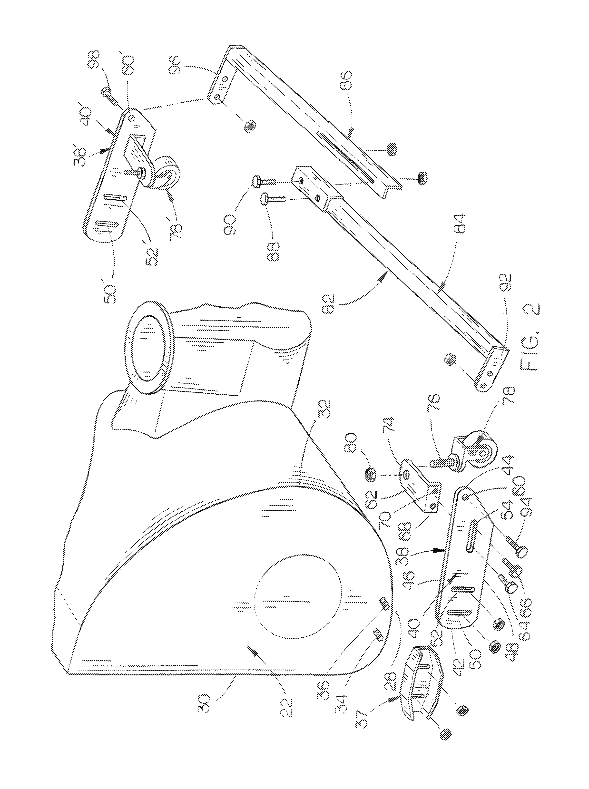
[0021]Auger housing 18 includes an open forward end into which the snow is passed and a first side wall 22 and a second side wall 24. For purposes of description, side wall 2...


PUM


Abstract

A caster wheel assembly is disclosed for a snowblower wherein a pair of caster wheel assemblies are secured to the opposite sides of the auger housing of the snowblower in a manner wherein the caster wheels thereof are positioned inwardly of the sides of the auger housing and are positioned rearwardly of the rearward end of the auger housing.

Description

CROSS-REFERENCE TO RELATED APPLICATION[0001]This is a non-provisional application based upon Provisional Application Ser. No. 61 / 553,514, filed Oct. 31, 2011, entitled A CASTER WHEEL ASSEMBLY FOR A SNOWBLOWER.BACKGROUND OF THE INVENTION[0002]1. Field of the Invention[0003]This invention relates to a snowblower and more particularly to a caster wheel assembly which is secured to each of the side walls of the auger housing of the snowblower. The caster wheels of the caster wheel assemblies are positioned rearwardly of the auger housing and are positioned inwardly of the side walls of the auger housing.[0004]2. Description of the Related Art[0005]Conventional walk-behind snowblowers include a wheeled frame means having an auger housing at the forward end thereof with the auger housing having an open forward end, a rearward end, a first side wall and a second side wall with the side walls having forward and rearward ends. In the conventional walk-behind snowblowers, a skid shoe is secur...

Claims


Application Information

Patent Timeline
Patent Type & Authority Patents(United States)
IPC IPC(8): E01H5/09
CPCE01H5/09E01H5/098
Inventor MORSE, LANNY E.SPERRY, ROYCE E.
Owner SPERRY CAROL F
Why Eureka
Try Eureka