Methods and apparatus for interactive debugging on a non-preemptible graphics processing unit

a graphics processing unit and interactive debugging technology, applied in the field of debugging, can solve the problems of introducing additional delays or inconsistencies, and affecting the debugging effect of the modified program,

Active Publication Date: 2013-10-29
NVIDIA CORP
View PDF15 Cites 24 Cited by
  • Summary
  • Abstract
  • Description
  • Claims
  • Application Information

AI Technical Summary

Benefits of technology

[0011]One advantage of the disclosed approach is that a computer used for debugging purposes may use a single GPU for both hardware debugging and screen updates. Other advantages include the ability to debug non-deterministic applications and the ability to debug programs for which no source code is available.

Problems solved by technology

While such techniques may be beneficial for detecting some types of errors, these techniques have many disadvantages.
Requiring a user to execute a modified program may not allow a user to analyze the program in real-time.
If the program is not deterministic, then re-executing the program may display inconsistent values for variables.
Further, re-executing the program may require large memory transfers in order to reset state variables, which may introduce additional delays or inconsistencies.
Modifying the program may also hide some errors caused by the specific timing of instructions as executed by the system or change the order of the instruction stream generated by the compiler, thereby leading to entirely different results.
Further, a user may not be able to analyze the efficiency of the unmodified program to determine where some types of processing bottlenecks are occurring.
However, because the software emulator merely simulates the targeted platform, debugging certain transient errors caused by asynchronous execution of instructions may be difficult using the software emulator.
Furthermore, the software emulator may behave differently than the targeted hardware platform due to bugs inherent in the software emulator or tradeoffs between simulation performance and accuracy, thus confounding the debugging issue.

Method used


Image

  • Methods and apparatus for interactive debugging on a non-preemptible graphics processing unit
  • Methods and apparatus for interactive debugging on a non-preemptible graphics processing unit
  • Methods and apparatus for interactive debugging on a non-preemptible graphics processing unit

Examples


Embodiment Construction

[0021]In the following description, numerous specific details are set forth to provide a more thorough understanding of the present disclosure. However, it will be apparent to one of skill in the art that the invention may be practiced without one or more of these specific details.

System Overview

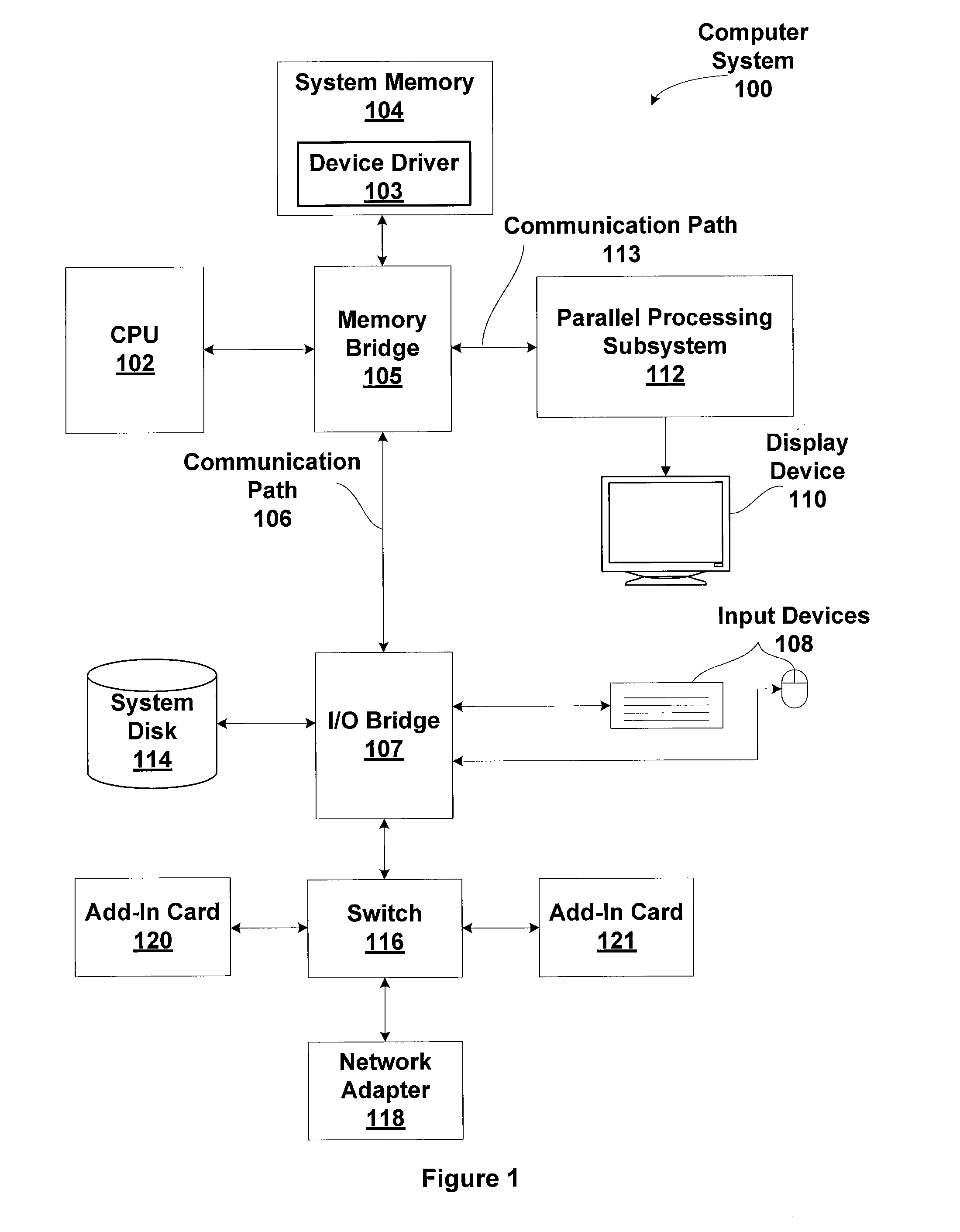
[0022]FIG. 1 is a block diagram illustrating a computer system 100 configured to implement one or more aspects of the present disclosure. Computer system 100 includes a central processing unit (CPU) 102 and a system memory 104 communicating via an interconnection path that may include a memory bridge 105. Memory bridge 105, which may be, e.g., a Northbridge chip, is connected via a bus or other communication path 106 (e.g., a HyperTransport link) to an I / O (input / output) bridge 107. I / O bridge 107, which may be, e.g., a Southbridge chip, receives user input from one or more user input devices 108 (e.g., keyboard, mouse) and forwards the input to CPU 102 via communication path 106 and memory ...


PUM


Abstract

Systems and methods are disclosed for performing interactive debugging of shader programs using a non-preemptible graphics processing unit (GPU). An iterative process is employed to repeatedly re-launch a workload for processing by the shader program on the GPU. When the GPU encounters a hardware stop event, such as by reaching a breakpoint in any thread of the shader program, encountering a hardware exception, or failing a software assertion in the shader program, the state of any executing threads is saved, graphics memory is copied to system memory, and any currently executing threads are killed to enable the GPU to process graphics data for updating a display device. Each pass of the workload may result in incrementally more data being processed. In effect, the changing state and variable data resulting from each pass of the workload has the effect that the debugger is incrementally stepping through the shader program.

Description

BACKGROUND[0001]1. Technical Field[0002]The present disclosure generally relates to debugging, and more specifically to methods and apparatus for interactive debugging on a non-preemptible graphics processing unit (GPU).[0003]2. Description of the Related Art[0004]Conventional debugging tools provide the capability to halt execution of a program at a given point in the program and evaluate the processor context (i.e., memory, registers, etc.) at that point in the program using a user interface of some type, typically a graphical user interface displayed on a monitor coupled to the debugging platform. Typically, debugging tools are categorized as software implementations or hardware implementations.[0005]Software debugging includes many techniques for detecting errors in a program. One technique for debugging a program is to modify the program so that various variable values are written to an alternate location or replace the normal program output during execution of the program. The...

Claims


Application Information

Patent Timeline
Patent Type & Authority Patents(United States)
IPC IPC(8): G06F9/44
CPCG06F11/3632
Inventor BALIGA, AVINASH BANTVALSMITH, GREGORY PAUL
Owner NVIDIA CORP
Why Eureka
Try Eureka