
Determining borehole corrected formation on properties

a technology of properties and measurement methods, applied in the direction of seismology, instrumentation, and waterlogging using reradiation, can solve the problems of difficult to use or interpret the measurements to infer formation properties, complicated derivation of formation conductivity from received signals, and inability to accurately determine the conductivity of measurements

Inactive Publication Date: 2013-10-29
SCHLUMBERGER TECH CORP
View PDF43 Cites 8 Cited by
  • Summary
  • Abstract
  • Description
  • Claims
  • Application Information

AI Technical Summary

Benefits of technology

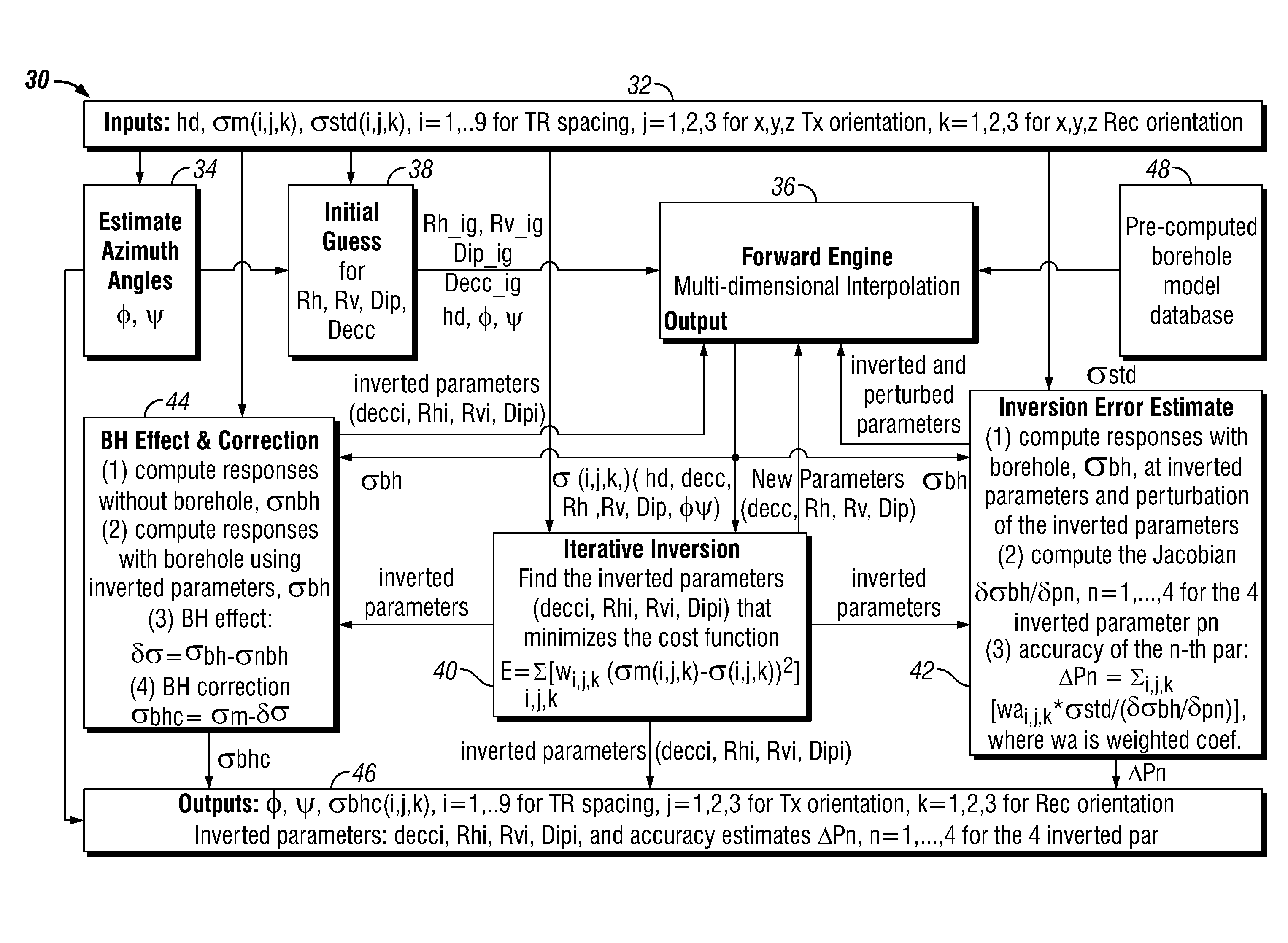
This patent describes a method to determine formation properties in a borehole using measurements made by a logging tool. The method involves creating a modeled conductivity tensor for the formation and optimizing its parameters to match the measurements. Once the parameters are optimized, the conductivity tensor is computed to correct for the effects of the borehole. Using this corrected conductivity tensor and the optimized parameters, the formation properties can be determined. The technical effects of this invention include improved accuracy in determining formation properties and better drilling performance.

Problems solved by technology

However, the existence of a borehole complicates the derivation of formation conductivity from the received signals.
The most prevalent complication that affects the derivation of formation conductivity from the received signals arises from the presence of drilling fluids in the borehole surrounding the induction instrument.
In addition, tool properties may affect the measurements conductivity tensor.
Unless the borehole / tool effects are removed or otherwise compensated for, it is hard to use or interpret the measurements to infer formation properties.

Method used


Image

  • Determining borehole corrected formation on properties
  • Determining borehole corrected formation on properties
  • Determining borehole corrected formation on properties

Examples


Embodiment Construction

[0042]Refer now to the drawings wherein depicted elements are not necessarily shown to scale and wherein like or similar elements are designated by the same reference numeral through the several views.

[0043]As used herein, the terms “up” and “down”; “upper” and “lower”; and other like terms indicating relative positions to a given point or element are utilized to more clearly describe some elements of the embodiments of the invention. Commonly, these terms relate to a reference point as the surface from which drilling operations are initiated as being the top point and the total depth of the well being the lowest point.

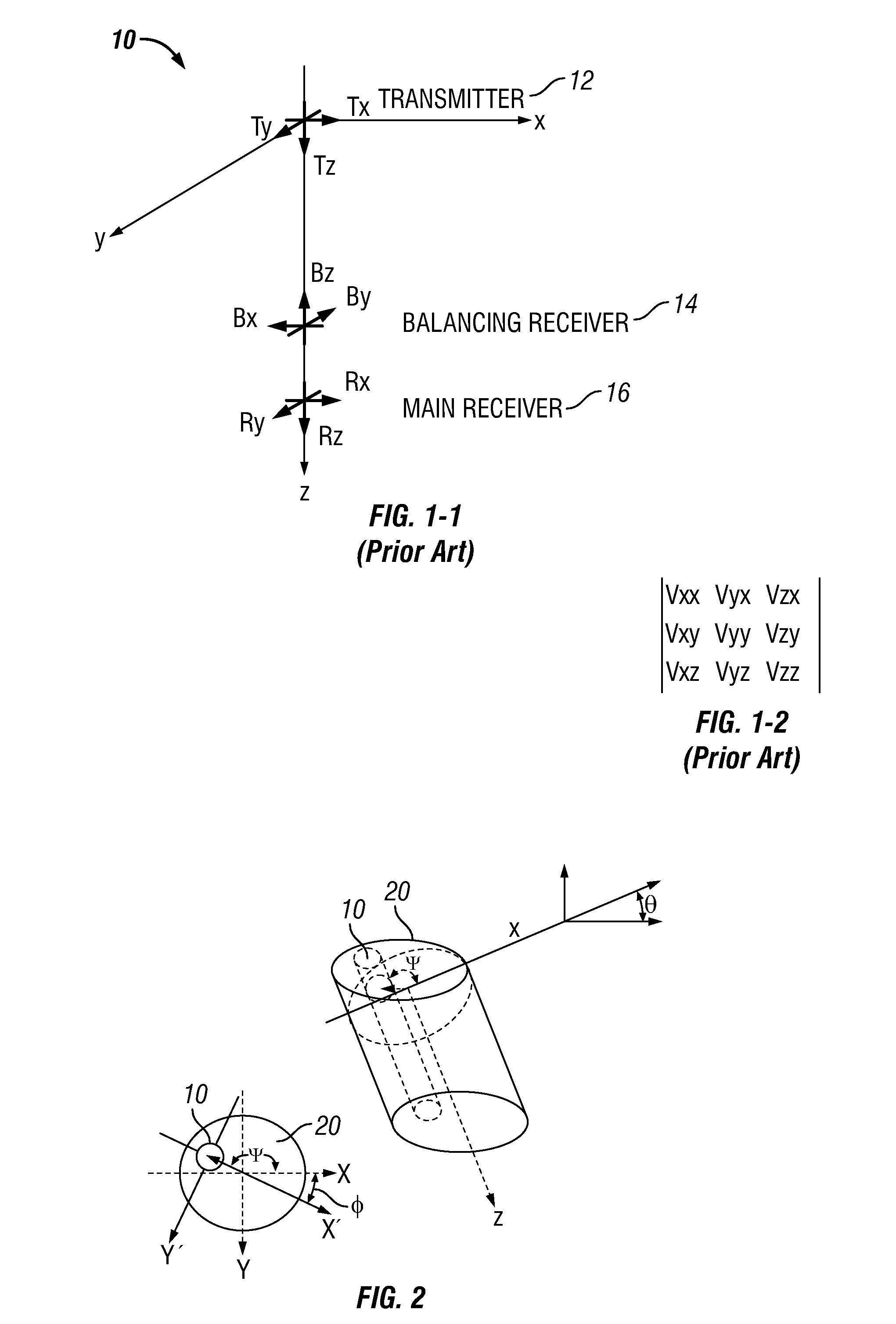
[0044]FIG. 1-1 is an example of a 3D tri-axial induction tool, indicated generally by numeral 10, comprising transmitter 12, balancing receiver 14 and main receiver 16, wherein the antennas are represented by their respective dipole moments. A 3D tri-axial induction tool measures voltages from which a nine component apparent conductivity tensor (σm(j, k), j, k=1, 2, 3...


PUM


Abstract

A method to determine one or more borehole corrected formation properties using measurements made using a logging tool disposed in a borehole penetrating an earth formation is disclosed. The measurements are used to determine an apparent conductivity tensor for the formation and, for a set of parameters, a parameter value for each parameter in a subset of the set of parameters. A parameter value for each parameter in the set of parameters not in the subset is provided and a borehole-inclusive modeled conductivity tensor is computed. The apparent conductivity tensor and the borehole-inclusive modeled conductivity tensor are iteratively used to optimize the parameter values, and the optimized parameter values are used to compute an optimized conductivity tensor. A borehole corrected conductivity tensor is computed using the optimized conductivity tensor, and the borehole corrected formation properties are determined using the borehole corrected conductivity tensor and / or the optimized parameter values.

Description

[0001]This application claims the benefit of U.S. Provisional Patent Application Nos. 60 / 916,616, filed on May 8, 2007 and 60 / 950,708, filed on Jul. 19, 2007.TECHNICAL FIELD[0002]The present invention relates in general to the field of measuring properties of downhole environments and, more specifically, to resistivity tool analysis.BACKGROUND[0003]Resistivity tools are used in the oil and gas industry to determine the resistivity of earth formations surrounding a borehole. Conventional induction tools, for example, work by using a transmitting coil (transmitter) to set up an alternating magnetic field in the earth formations. This alternating magnetic field induces eddy currents in the formations. One or more receiving coils (receivers), disposed at a distance from the transmitter, detect the current flowing in the earth formation. The magnitudes of the received signals are proportional to the formation conductivity. Therefore, formation conductivities may be derived from the recei...

Claims


Application Information

Patent Timeline
IPC IPC(8): G01V3/38
CPCG01V3/38G01V1/50G01V13/00
Inventor WU, PETER T.WANG, HANMINGMINERBO, GERALD N.
Owner SCHLUMBERGER TECH CORP
Learn More