
System with position-determination for lifting columns, and method therefor

a technology of position determination and lifting column, applied in the field of lifting system, can solve the problem of user walking through the space along the individual lifting column, and is therefore unnecessary, and achieve the effect of increasing the flexibility of known system

Active Publication Date: 2013-10-29
STERTIL
View PDF13 Cites 42 Cited by
  • Summary
  • Abstract
  • Description
  • Claims
  • Application Information

AI Technical Summary

Benefits of technology

The present invention aims to provide a system that can lift and lower an object, such as a vehicle, with increased flexibility compared to existing systems.

Problems solved by technology

The user walking through the space along the individual lifting columns is hereby unnecessary.

Method used


Image

  • System with position-determination for lifting columns, and method therefor
  • System with position-determination for lifting columns, and method therefor
  • System with position-determination for lifting columns, and method therefor

Examples


Embodiment Construction

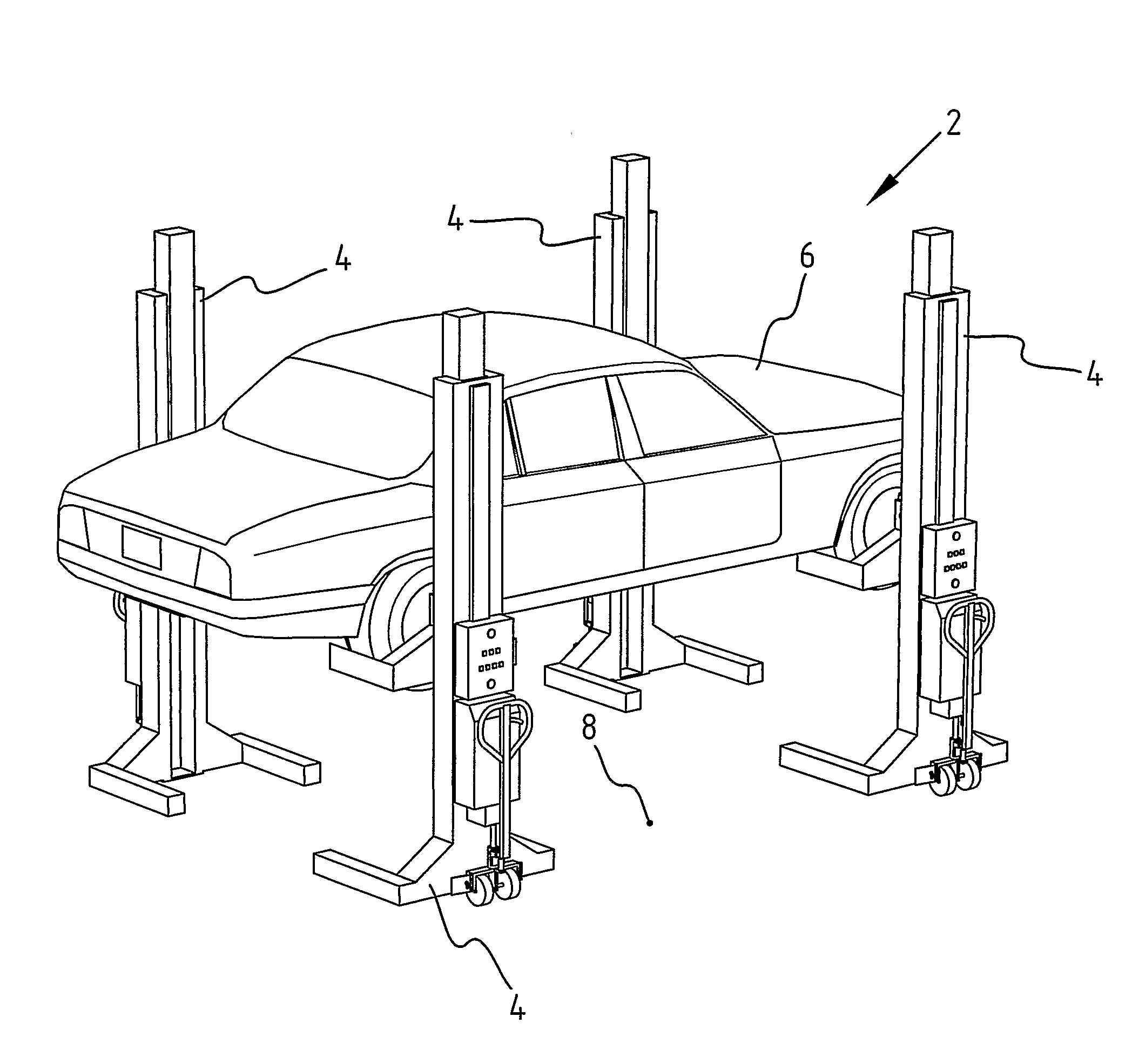
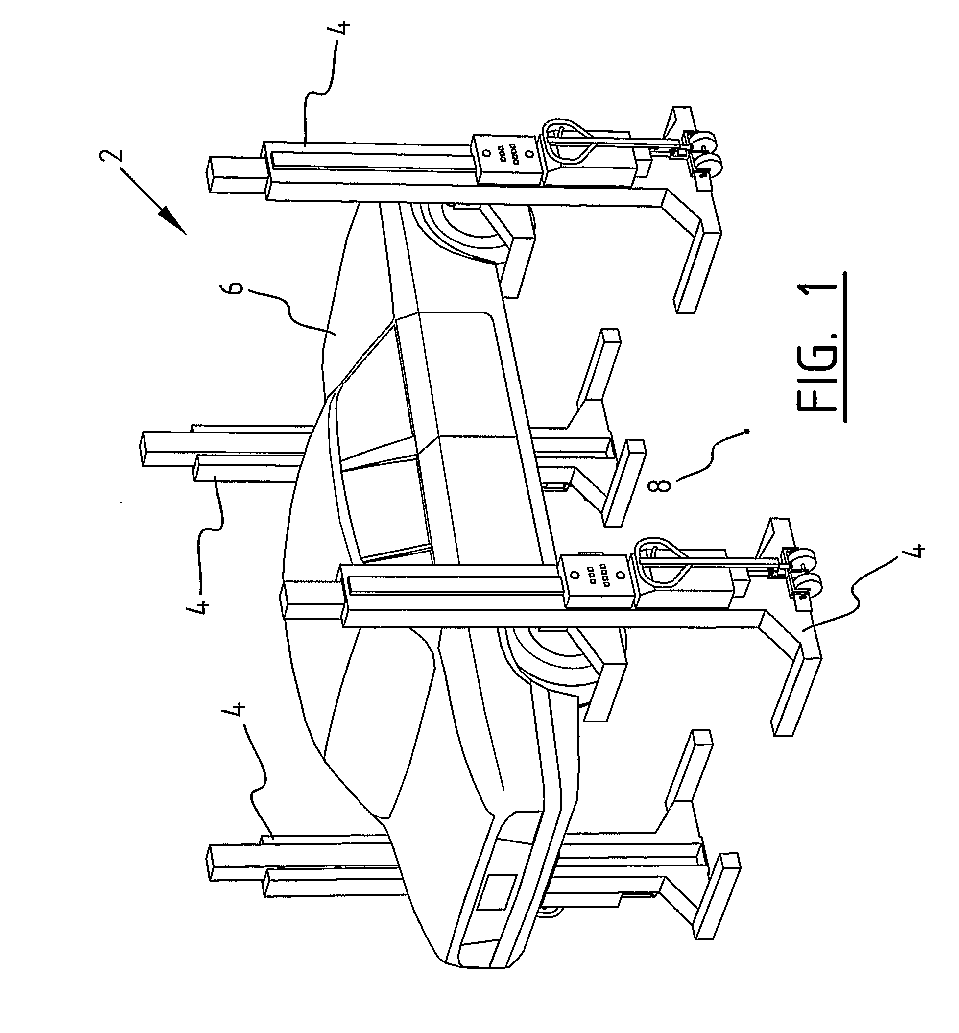
[0033]A lifting system 2 (FIG. 1) is assembled from four lifting columns 4. Lifting columns 4 can be connected to each other radiographically or via cables for the exchange of control signals. Lifting system 2 serves to lift a vehicle 6 and re-place it on the ground 8. The lifting system thus has an ascent mode and a descent mode in which lifting columns 4 must run as synchronously as possible.

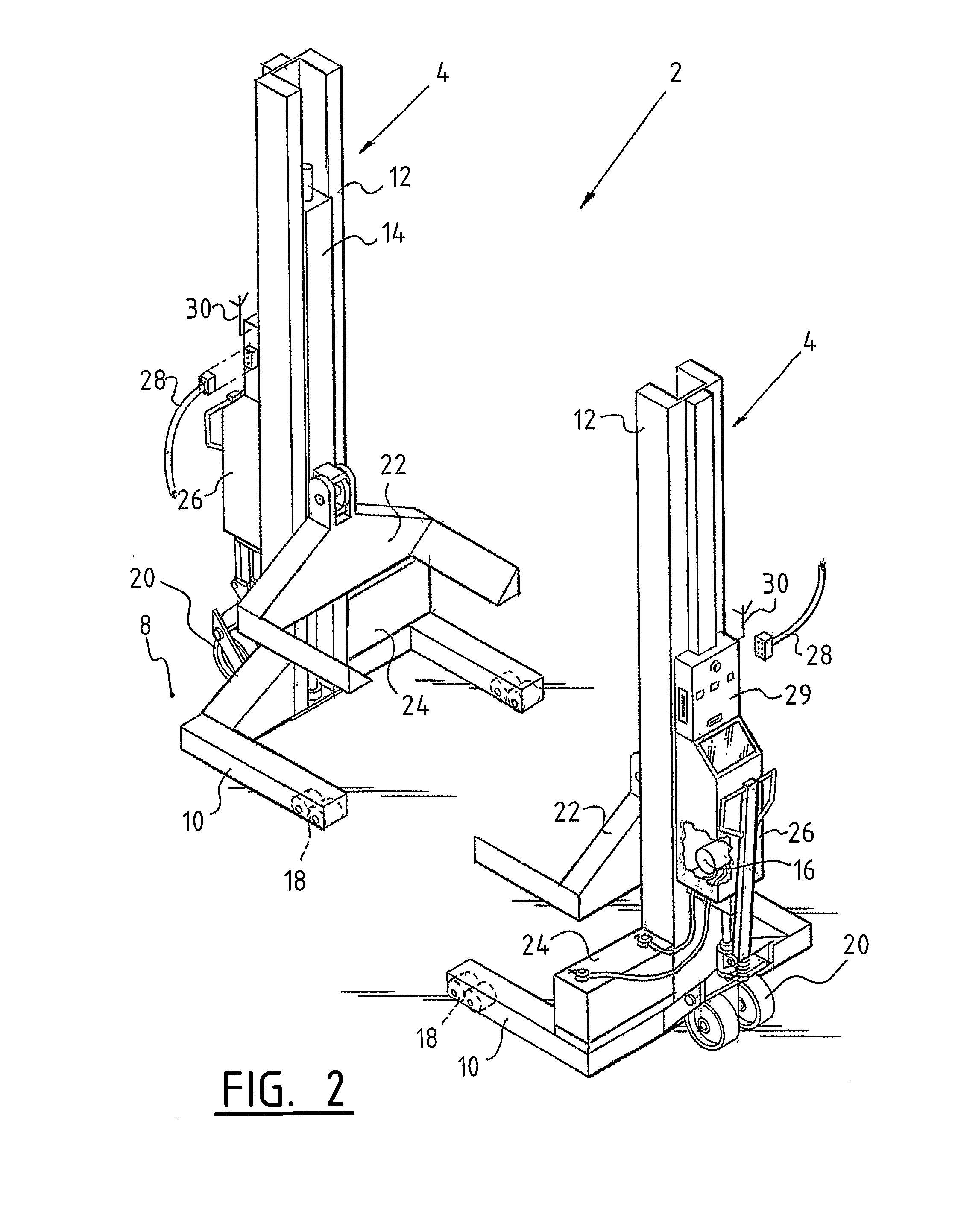
[0034]Each of the lifting columns 4 (FIG. 2) is provided with a foot 10 which can be placed on ground 8, and a mast part 12, wherein a carriage 14 is movable up and downward along mast part 12 under the influence of a drive in the form of a motor 16. Foot 10 and mast part 12 thus form a kind of frame which can travel over rollers 18 and wheels 20. Wheels 20 can be raised along the frame, whereby the foot comes to lie on the ground and there is no danger of the lifting column 4 being able to move away while it is bearing a load. Arranged on carriage 14 is a carrier 22 which is designed to engag...


PUM


Abstract

A system and method for lifting and lowering an object such as a vehicle, comprising: at least two lifting columns; communication means for communication with the at least two lifting columns; position-determining means for carrying out a position determination for each of the at least two lifting columns; selection means for selecting at least one of the lifting columns on the basis of the position determinations; and at least one control unit co-acting with the communication means during use for the purpose of controlling the lifting columns selected with the selection means.

Description

BACKGROUND OF THE INVENTION[0001]1. Field of the Invention[0002]The present invention relates to a system for lifting and lowering an object such as a vehicle. The system provides position-determination for the lifting columns.[0003]2. Prior Art[0004]The systems known in practice, which make use of lifting columns for lifting and lowering of a vehicle, usually make use of lifting columns at a fixed position. In such a system the lifting columns co-act in a fixed configuration and can be controlled from one lifting column or another central point. Such a system is less flexible and is unsuitable for adjusting for instance a number of lifting columns to the type of vehicle which has to be lifted and lowered. Such vehicles are for instance a car, a van and trucks with different wheel bases and provided with two or more axles.[0005]Other known systems make use of mobile lifting columns. The flexibility of such a system is hereby increased, since the number and the position of the liftin...

Claims


Application Information

Patent Timeline
Patent Type & Authority Patents(United States)
IPC IPC(8): B66F3/46
CPCB66F3/46
Inventor DE JONG, JURJEN JANWANSCHERS, LAMBERT HENDRIKUS
Owner STERTIL
Learn More