
Catheter and medical assembly

a catheter and medical technology, applied in the field of catheter, can solve the problems of hardly predicting if resonance will occur, excessive heating especially at the tips, and inability to safely perform electrophysiological (ep) interventions under magnetic resonance (mr) guidance, so as to reduce the current flowing in the wire(s) of the electrical connection, or stop the effect of current flowing in the wir

Active Publication Date: 2013-10-22
KONINK PHILIPS ELECTRONICS NV
View PDF12 Cites 3 Cited by
  • Summary
  • Abstract
  • Description
  • Claims
  • Application Information

AI Technical Summary

Benefits of technology

[0011]It is an object of the present invention to provide a catheter and a medical assembly using such a catheter which can be used during medical interventions under MR guidance without the risk that the electrical connection of the catheter becomes excessively hot due to resonance at the operating frequency of the MR scanner.
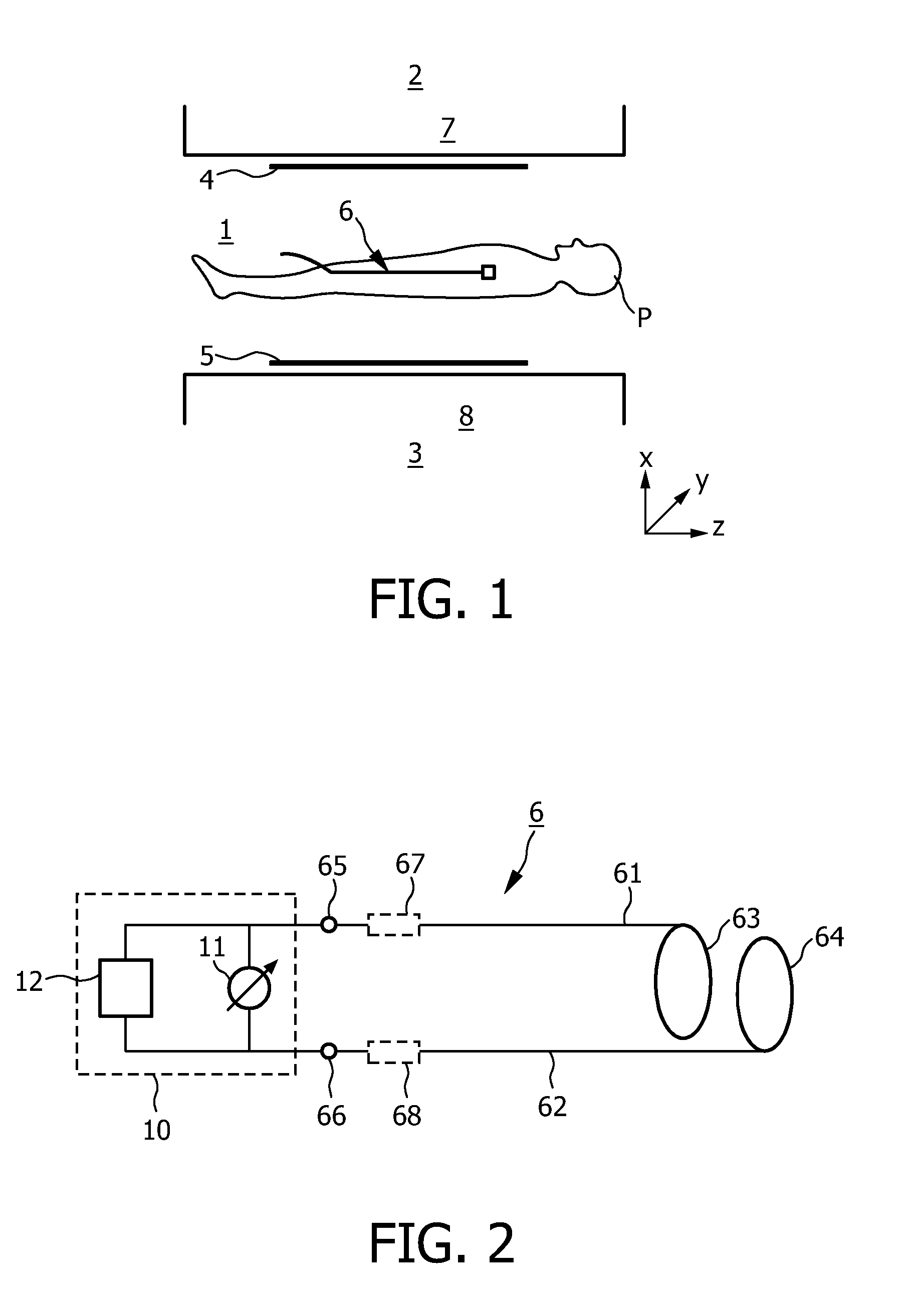
[0022]To avoid any risk that too high currents or voltages my cause any damage to a patient's health during an intervention, a preferred embodiment of the catheter comprises a current sensing unit for sensing the electrical current flowing in the electrical connection at the distal side of the catheter and for transmitting a sensing signal indicative of the sensed current to an external current control unit. Thus, a current leakage between the catheter input and the catheter tip can be recognized, and countermeasures can be taken by the current control unit, e.g. the current flowing in the wire(s) of the electrical connection can be reduced or stopped.

Problems solved by technology

So far electrophysiologic (EP) interventions cannot be performed safely under magnetic resonance (MR) guidance due to the risk of radio frequency (RF) heating.
This connection can become resonant at the operating frequency of the MR scanner and thus act as an antenna for the applied RF fields, leading to excessive heating especially at the tips.
As a consequence it is hardly possible to predict if resonance will occur during an intervention, since the length of wire inside the patient as well as the surrounding of the wire changes continuously.
However, said carbon is not sufficiently RF-safe for medical applications in the field of MR.

Method used


Image

  • Catheter and medical assembly
  • Catheter and medical assembly
  • Catheter and medical assembly

Examples


Embodiment Construction

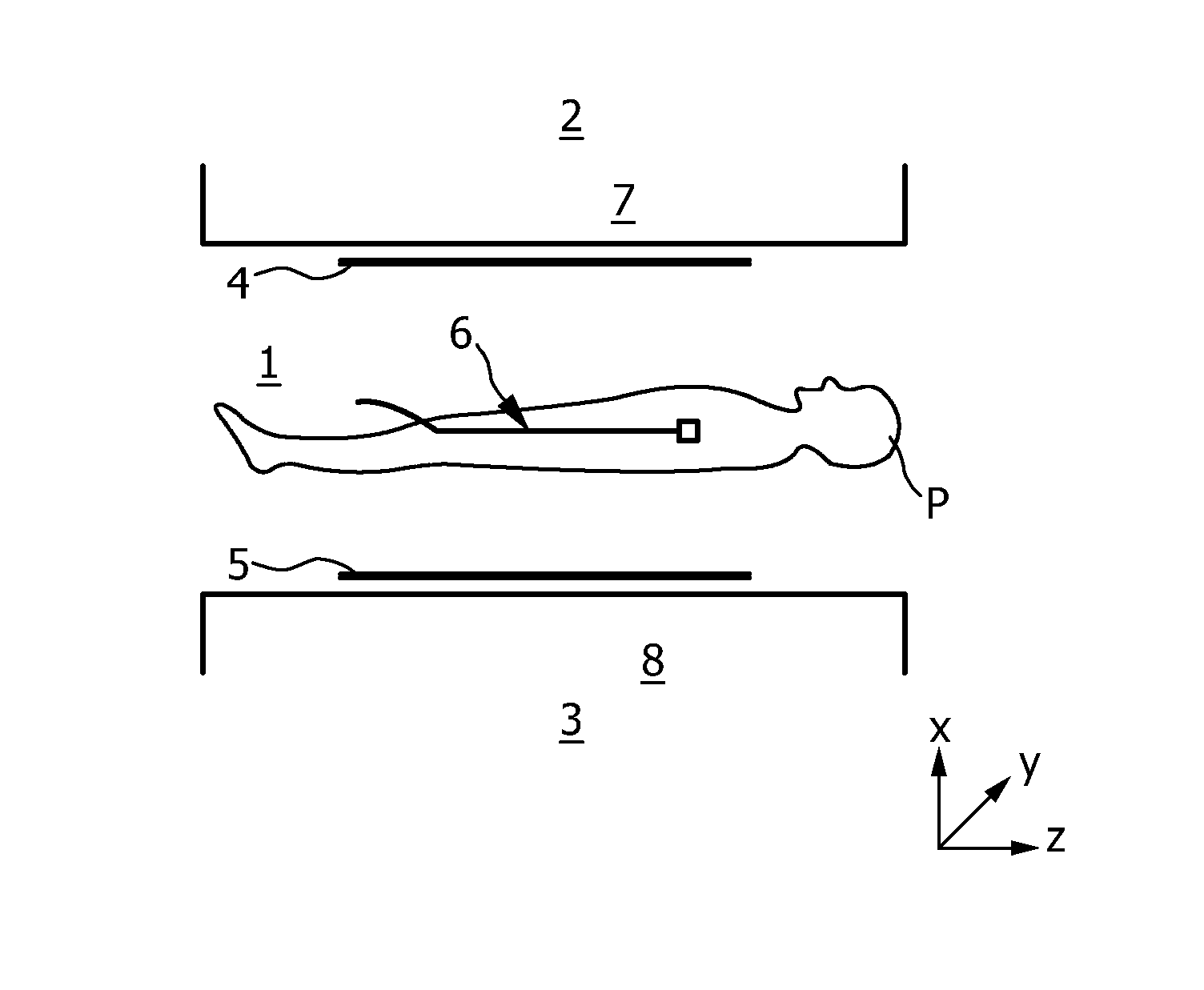
[0030]FIG. 1 exemplarily shows components of an open MR imaging apparatus which are of essential importance for the generation and reception of magnetic fields in an examination zone 1. Above and underneath the examination zone 1 there are provided respective magnet systems 2, 3 which generate an essentially uniform main magnetic field (B0 field for magnetizing the object to be examined, that is, for aligning the nuclear spins) whose magnetic flux density (magnetic induction) may be in the order of magnitude of between some tenths of Tesla to some Tesla. The main magnetic field essentially extends through a patient P in a direction perpendicular to the longitudinal axis of the patient (that is, in the x direction).

[0031]Planar or at least approximately planar RF conductor structures (resonators) in the form of RF transmission coils 4 (“body coils”) are provided for generating RF pulses (B1 field) of the MR frequency whereby the nuclear spins are excited in the tissue to be examined,...


PUM


Abstract

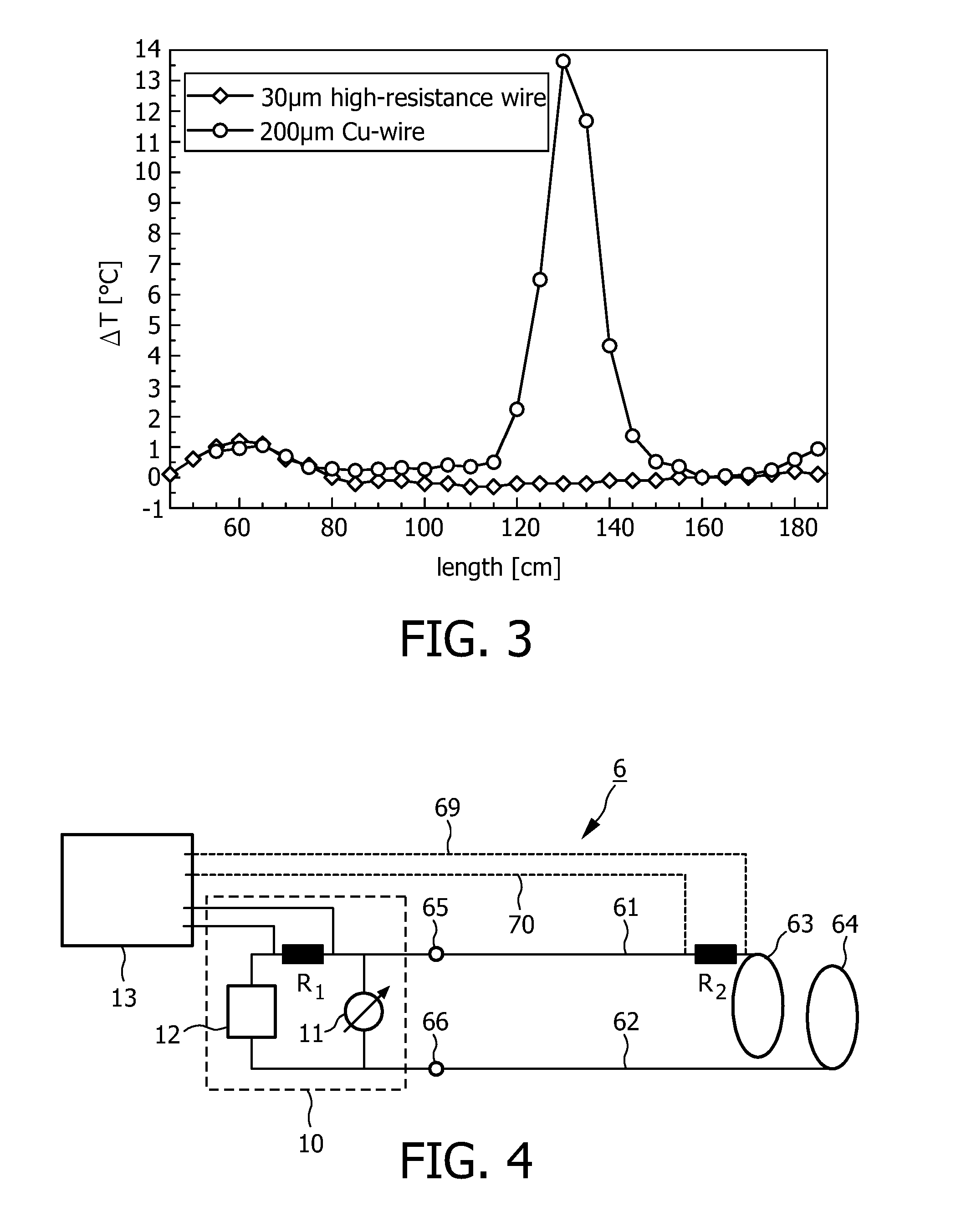
The present invention relates to a catheter (6) comprising: a connector (65, 66) at a proximal side of the catheter for connecting the catheter to an external signal transmission / receiving unit (10) for transmitting and / or receiving signals, an electrode (63, 64) at a distal side of the catheter, and an electrical connection including an electrical wire (61, 62) for electrically connecting the electrode and the connector for the transmission of signals between the electrode and the connector, wherein the electrical connection has a high electrical resistance of at least 1 kΩ, in particular of at least 5 kΩ. Thus, the present invention provides a solution to prevent excessive heating during EP interventions under MR guidance by using highly resistive wires and or lumped resistors as connections within catheters.

Description

FIELD OF THE INVENTION[0001]The present invention relates to a catheter comprising:[0002]a connector at a proximal side of the catheter for connecting the catheter to an external signal transmission / receiving unit for transmitting and / or receiving signals,[0003]an electrode at a distal side of the catheter, and[0004]an electrical connection including an electrical wire for electrically connecting the electrode and the connector for the transmission of signals between the electrode and the connector.[0005]Further, the present invention relates to a medical assembly comprising such a catheter.BACKGROUND OF THE INVENTION[0006]So far electrophysiologic (EP) interventions cannot be performed safely under magnetic resonance (MR) guidance due to the risk of radio frequency (RF) heating. For EP procedures it is necessary to monitor the intracardiac electrocardiogram (IECG) (“mapping”) and / or to stimulate the heart (“pacing”). Both require an electrical connection to electrodes on the cathet...

Claims


Application Information

Patent Timeline
Patent Type & Authority Patents(United States)
IPC IPC(8): A61B5/05A61B5/308
CPCA61B5/042A61B5/0428A61N1/056A61N1/3625A61B5/055A61B2562/222A61N1/3718A61N2001/086G01R33/287A61N1/086A61B5/283A61B5/30
Inventor LIPS, OLIVERDAVID, BERNDGLEICH, BERNHARDKRUEGER, SASCHAWEISS, STEFFENWIRTZ, DANIEL
Owner KONINK PHILIPS ELECTRONICS NV
Learn More