
Radio communication device and signal processing method

a communication device and signal processing technology, applied in the direction of transmission monitoring, diversity/multi-antenna system, polarisation/directional diversity, etc., can solve the problem of insufficient time for measuring the fading rate, and achieve the effect of improving the so accuracy of signal processing and reducing the time for measuring

Inactive Publication Date: 2013-10-22
KYOCERA CORP
View PDF16 Cites 0 Cited by
  • Summary
  • Abstract
  • Description
  • Claims
  • Application Information

AI Technical Summary

Benefits of technology

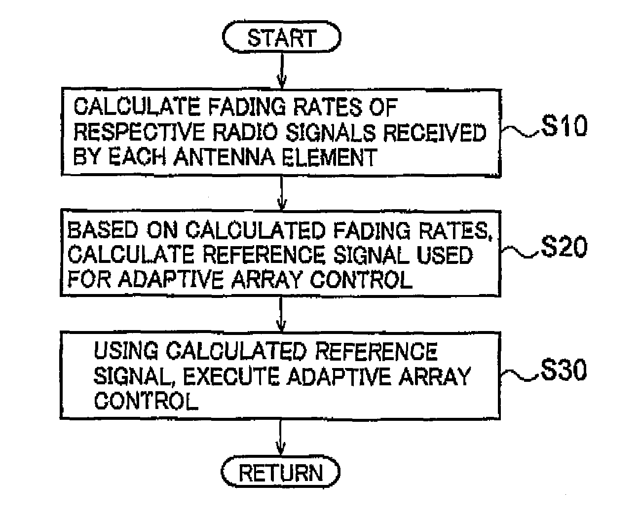
The present invention provides a radio communication device and a signal processing method that can improve the accuracy of signal processing, such as adaptive array control, while reducing the time required to measure the fading rate of a radio signal. By measuring the fading rates of multiple antenna elements simultaneously, the accuracy of fading rate measurement can be improved even when there is insufficient time to secure a sufficient number of measurements. This allows for improved performance and reliability in radio communication, particularly in situations where the radio communication terminal is moving at high speed.

Problems solved by technology

However, there is the following problem in the conventional is method in which the radio base station corrects the transmission weight based on a Doppler frequency, namely, a fading rate, of a radio signal received from the radio communication terminal through the array antenna.
However, there is a case where enough time for measuring the fading rates cannot be secured, such as in the initial connection of a radio communication terminal to the radio base station.

Method used


Image

  • Radio communication device and signal processing method
  • Radio communication device and signal processing method
  • Radio communication device and signal processing method

Examples


Embodiment Construction

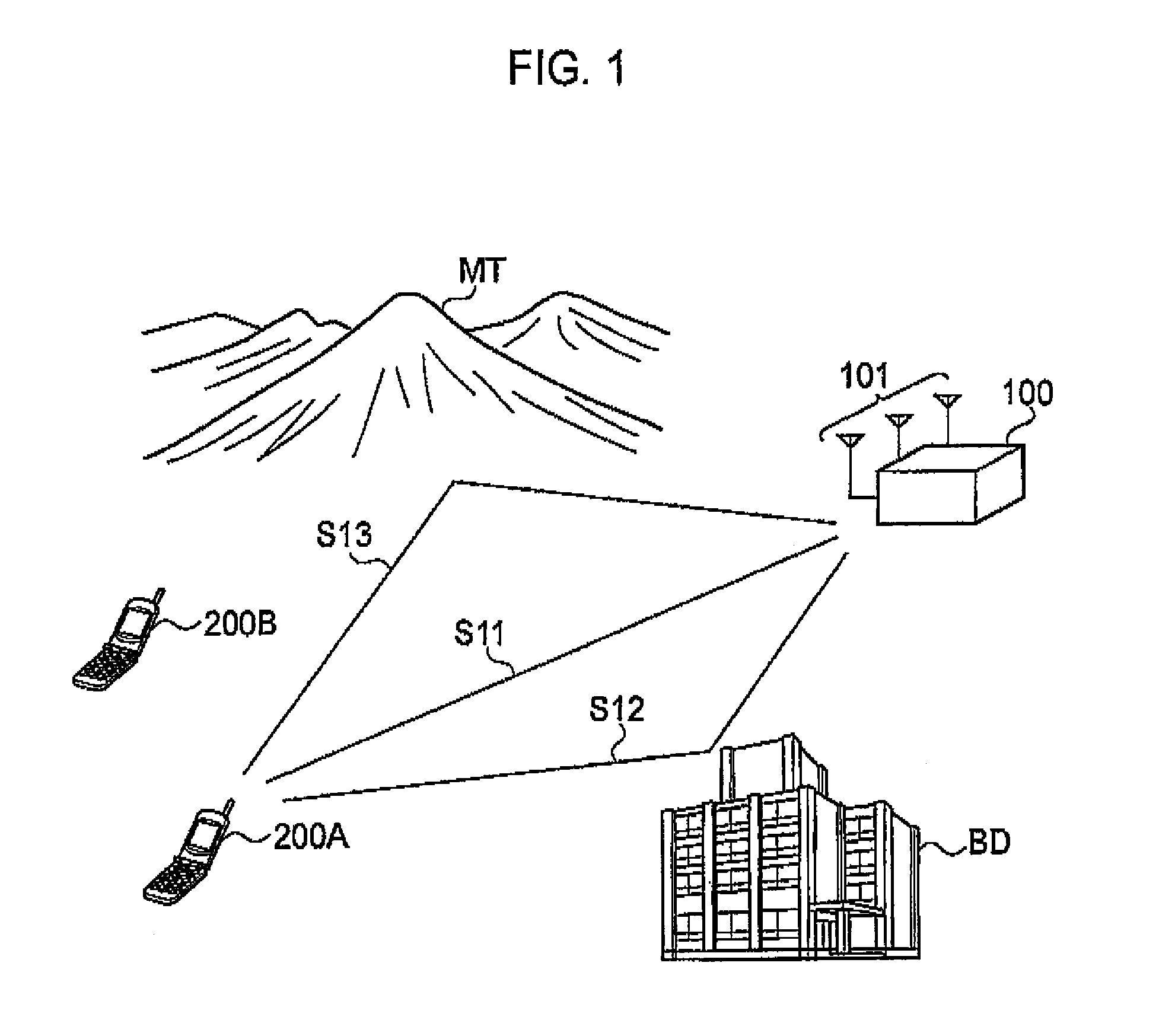
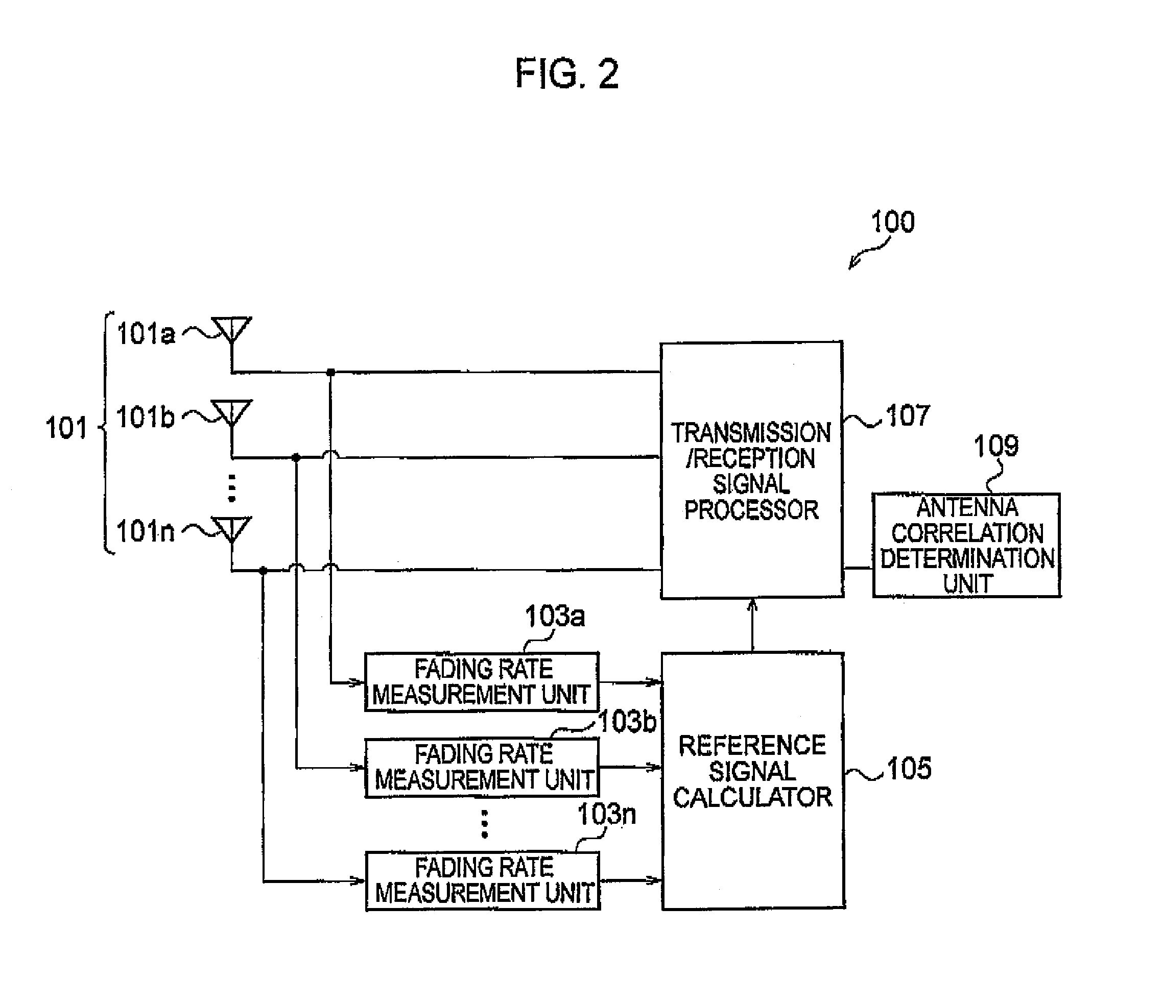
[0026]Next, an embodiment of the present invention is described. Specifically, descriptions are given for (1) an overall schematic configuration of a radio communication system, (2) a functional block configuration of a radio communication device, (3) a function of a reference signal output unit, (4) an operation of the radio communication device, (5) advantageous effects, and (6) other embodiments.

[0027]Note that, throughout the drawings, the same or like parts bear the same or like reference numerals. It should be noted, however, that the drawings are schematic, and that the dimensional proportions and the like are different from their actual values.

[0028]Accordingly, specific dimensions and the like should be inferred based on the description given below. Moreover, dimensional relationships and proportions may differ from one drawing to another in some parts, of course.

(1) Overall Schematic Configuration of Radio Communication System

[0029]FIG. 1 is an overall schematic configurat...


PUM


Abstract

A radio base station 100 includes fading rate measurement units 103a to 103n configured to measure a fading rate of a radio signal for each of the antenna elements 101a to 101n, the radio signal being received through the antenna elements; and a reference signal calculator 105 configured to output a reference signal used in an adaptive control of the directivity of the array antenna 101. The reference signal calculator 105 outputs the reference signal on the basis of a plurality of fading rates measured by the fading rate measurement units 103a to 103n.

Description

CROSS-REFERENCE TO THE RELATED APPLICATIONS[0001]This application is a national stage of international application No. PCT / JP2008 / 058047, filed on Apr. 25, 2008, which also claims the benefit of priority under 35 USC 119 to Japanese Patent Application No. 2007-117789, filed Apr. 26, 2007, the entire contents of which are incorporated herein by reference.TECHNICAL FIELD[0002]The present invention relates to a radio communication device including an array antenna having multiple antenna elements and to a signal processing method used in the radio communication device.BACKGROUND ART[0003]Adaptive array control is implemented in a radio communication system, such as a mobile communication system, so that an increased number of radio communication terminals can be accommodated in the radio communication system, for example. In the adaptive array control, the directivity of an array antenna having multiple antenna elements is adaptively controlled by a radio communication device, such as ...

Claims


Application Information

Patent Timeline
Patent Type & Authority Patents(United States)
IPC IPC(8): H04M1/00H04B1/06H04B7/08H04B7/10
CPCH04B7/0865
Inventor OKINO, KENTATODA, TAKESHIYAMAZAKI, CHIHARU
Owner KYOCERA CORP
Learn More