
Ribbon microphone unit with symmetrical signal paths

a microphone unit and signal path technology, applied in the field of ribbon microphones, can solve the problems of generating noise, vulnerability to noise, and affecting the noise of ribbon microphone units, and achieve the effect of preventing noise generation

Inactive Publication Date: 2013-10-22
AUDIO-TECHNICA
View PDF6 Cites 2 Cited by
  • Summary
  • Abstract
  • Description
  • Claims
  • Application Information

AI Technical Summary

Benefits of technology

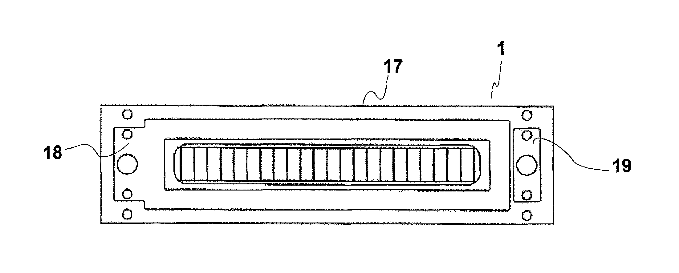
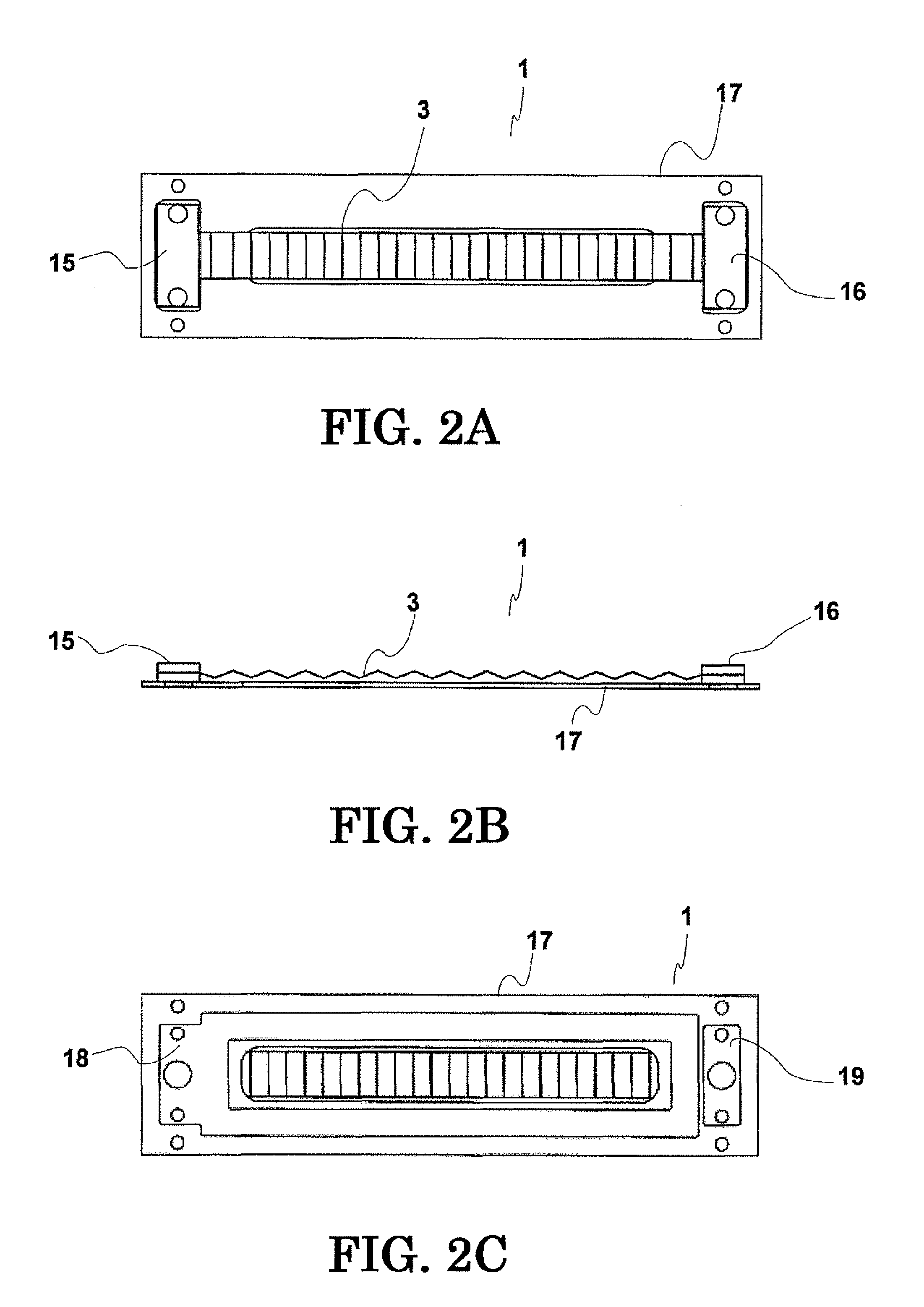
[0026]According to the present invention, the signal paths on the circuit substrate are symmetrical about the ribbon diaphragm. Thus, electrical signals induced in the ribbon diaphragm by an external magnetic field are offset and canceled on the signal paths, thereby preventing noise generation by the external magnetic field.

Problems solved by technology

The ribbon diaphragm 103 described above is lightweight and easy to move and is vulnerable to noise such as human breath and external mechanical vibrations.
In other words, the ribbon microphone unit may generate noise affected by an external magnetic field.
Although a power source is required to operate devices for amplifying and adjusting the output of the ribbon microphone (an amplifier and a mixer), such an AC power source (commercial AC power source) around the ribbon microphone generates an external magnetic field, thus generating noise.
It is difficult, however, to completely shield an external magnetic flux.
None of these patent literatures, however, can prevent the noise generation by the induction of the external magnetic field.

Method used


Image

  • Ribbon microphone unit with symmetrical signal paths
  • Ribbon microphone unit with symmetrical signal paths
  • Ribbon microphone unit with symmetrical signal paths

Examples


Embodiment Construction

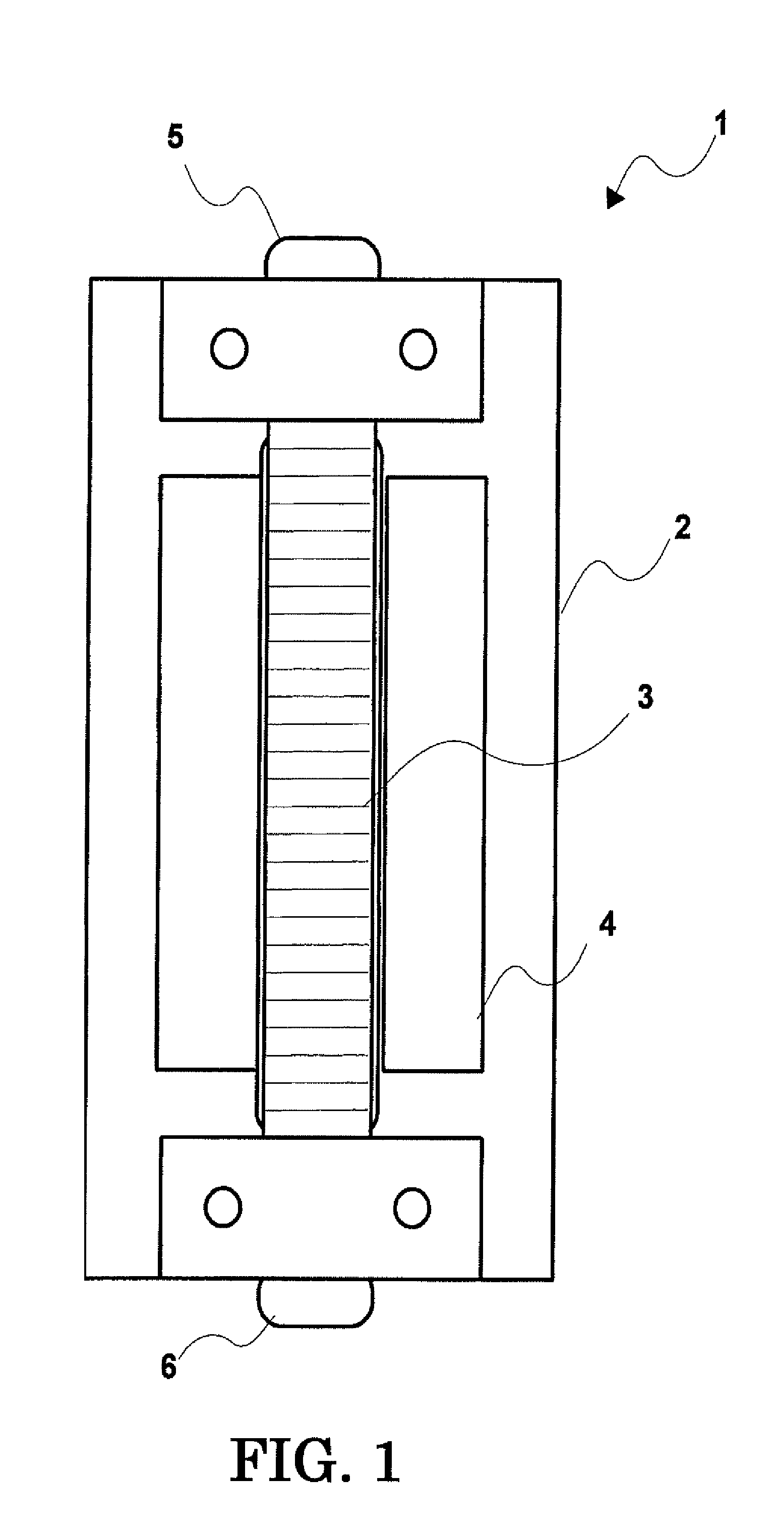
[0039]An embodiment of a ribbon microphone unit according to the present invention is explained below in detail with reference to the attached drawings. FIG. 1 is a front view of the ribbon microphone unit according to the embodiment of the present invention. The ribbon microphone unit 1 includes a platy support 2, a pair of magnets 4 mounted on the support 2, and a ribbon diaphragm 3 disposed in a magnetic field generated by the magnets 4. The support 2 has a vertically long window in a longitudinal direction thereof. The magnets 4 are disposed along the two longitudinal sides of the window to generate a uniform magnetic field between the magnets 4. The ribbon diaphragm 3 is disposed such that the direction of vibration crosses the magnetic field generated between the magnets 4. The magnets 4 are permanent magnets and are fixed at a predetermined distance. The magnets 4 are magnetized in the same width direction (the same horizontal direction in FIG. 1). Thus, a parallel magnetic f...


PUM


Abstract

A ribbon microphone unit includes a pair of magnets generating a magnetic field, a ribbon diaphragm disposed in the magnetic field generated by the magnets, and a circuit substrate provided with signal paths that conduct electrical signals generated by vibration of the ribbon diaphragm to output terminals. The signal paths are symmetrical about the longitudinal central axis of the ribbon diaphragm.

Description

BACKGROUND OF THE INVENTION[0001]1. Field of the Invention[0002]The present invention relates to a ribbon microphone unit including a ribbon-shaped diaphragm (hereinafter referred to as “ribbon diaphragm”) and a ribbon microphone including the ribbon microphone unit. Specifically, the present invention relates to a ribbon microphone unit and a ribbon microphone having a structure that can prevent generation of noise affected by an external magnetic field.[0003]2. Related Background Art[0004]A ribbon microphone including a ribbon diaphragm is one of the magnetoelectric microphones that collect sound by electromotive force developed by vibration of a diaphragm. The ribbon microphone, which was avoided for a long time due to low sensitivity, has started to be used by preference to collect sound of voice, traditional Japanese musical instruments, and string instruments because of its soft sound quality without discomfort. The ribbon microphone has recently drawn attention in recording s...

Claims


Application Information

Patent Timeline
Patent Type & Authority Patents(United States)
IPC IPC(8): H04R25/00
CPCH04R9/048H04R9/08H04R2410/03
Inventor AKINO, HIROSHI
Owner AUDIO-TECHNICA
Learn More