
Curtain control device

a control device and curtain fabric technology, applied in the field of curtain fabric control devices, can solve the problems of affecting the quality of curtain fabric, the effect of controlling the positioning of curtain fabric in rolling or unrolling might become worse, and the cost of the curtain fabric is pushed upward, so as to reduce the noise produced by the quick actuation of each part and the defective rate. , the effect of slowing down the roll-up speed of each curtain par

Inactive Publication Date: 2013-10-15
UNI-SOLEIL ENT CO LTD
View PDF3 Cites 14 Cited by
  • Summary
  • Abstract
  • Description
  • Claims
  • Application Information

AI Technical Summary

Benefits of technology

The present invention is about a curtain control device that can lock the curtain fabric when it is rolling or unrolling, and slow down the speed at which each part of the curtain rolls up. This device reduces the noise and defective rate caused by quick, sudden movement. A stroke setting device and a damper are used to control the opening range of the curtain fabric and slow down the roll-up speed of each part. This allows for better control and management of the curtain movement, resulting in a more effective reduction of noise and defects.

Problems solved by technology

However, the rotor of the conventional stroke setting device only has a single groove, and the snap-fit point in the groove only allows a slightly downward recess so as to maintain the smooth movement of the positioning member in the groove, thus the positioning member often fails to be locked effectively in position.
On the other hand, if the recessed depth at the snap-fit point is enlarged, the positioning member might be unable to escape from the snap-fit point so that effect of controlling the positioning of the curtain fabric in rolling or unrolling might become worse.
Moreover, this conventional device still needs the assistance of torsion spring, which will push cost upward.

Method used


Image

  • Curtain control device
  • Curtain control device
  • Curtain control device

Examples


Embodiment Construction

[0021]The objects, the technical contents and the expected effectiveness of the present invention will become more apparent from the detailed description of the preferred embodiment in conjunction with the accompanying drawings.

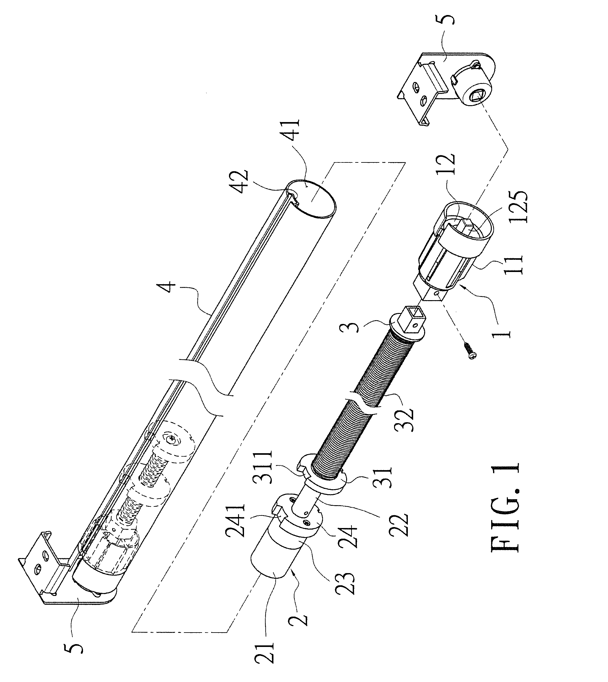
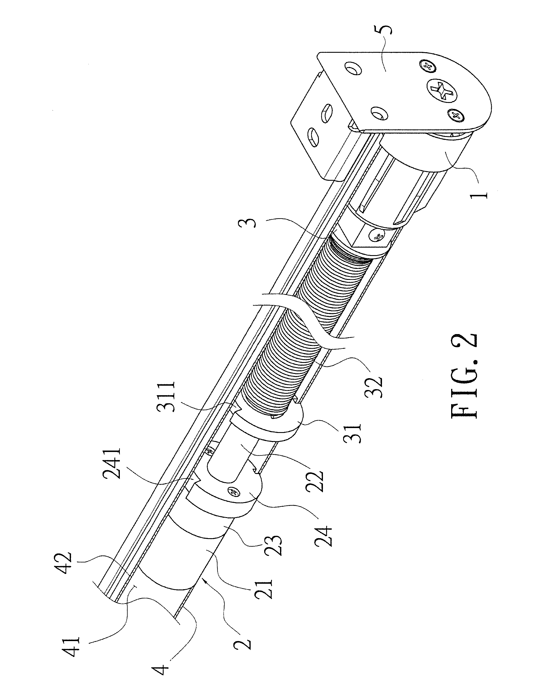
[0022]Firstly referring to FIGS. 1 and 2, the curtain control device of the present invention is mainly constituted of a stroke setting device (1), a damper (2), a curtain spindle rod (3) and a curtain spindle sleeve (4).

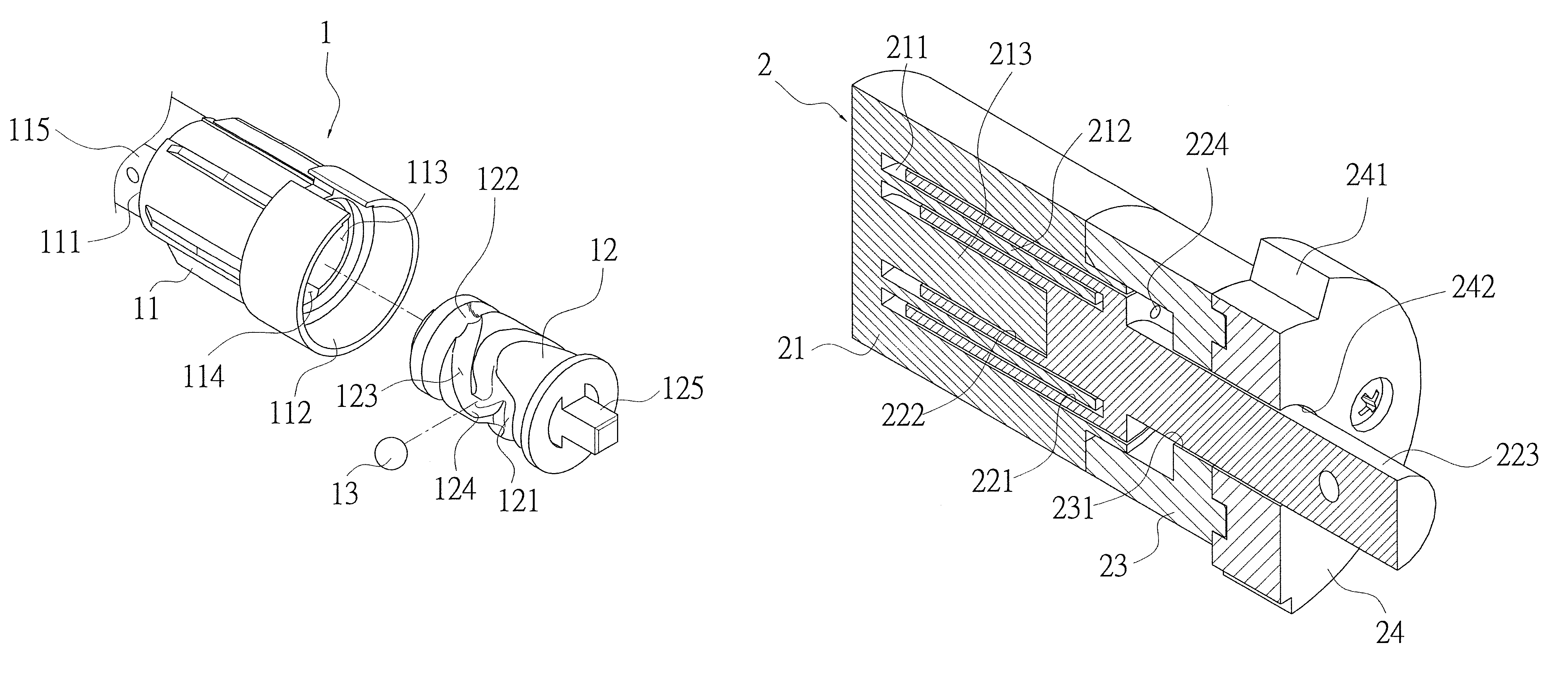
[0023]Referring to FIGS. 3 to 5, the stroke setting device (1) comprises a major body (11), a rotor (12) and a ball (13). The major body (11) of the stroke setting device (1) is a structure having a closed end (111) at one end, an opened end (112) at the other end, and a hollow portion (113) in its interior. A guiding groove (114) disposed along axial direction is provided on the inner wall of the hollow portion (113). An assembly portion (115) is provided on the closed end (111) of the major body (11) of the stroke setting device (1). Furthe...


PUM


Abstract

A curtain control device has a stroke setting device and a damper respectively assembled at both ends of a curtain spindle rod. A torsion element is further assembled on the curtain spindle rod. A curtain spindle sleeve is invaginated on the outside of the curtain spindle rod, the stroke setting device and the damper. The curtain spindle sleeve is assembled with the combination of the curtain spindle rod and the damper, and then a curtain fabric is assembled on the outside of the curtain spindle sleeve. In this manner, the opening range of the curtain fabric roll is controlled by the stoke setting device, and the roll-up speed of each part of the curtain fabric is slowed down by the damper so as to reduce effectively the noise produced by the quick actuation of each part and the defective rate.

Description

BACKGROUND OF THE INVENTION[0001]1. Field of the Invention[0002]The present invention relates to a curtain control device, particularly to a curtain control device enabling the setting of the opening range of the curtain fabric and effective slow-down of the roll-up speed of each part of the curtain, so as to reduce the noise produced by the quick actuation of each part and the defective rate.[0003]2. Brief Description of Prior Art[0004]Referring to Japanese Patent Gazette No. 3691372 entitled as “Roll-up Curtain Speed Reduction Device”, the device has a transverse mounting frame fixed on upper edge of the window, a winding rod provided within the transverse mounting frame, a curtain fabric rolled up on the winding rod, and a stroke setting device assembled with the winding rod. When user wants to adjust the range of rolling or unrolling of the curtain fabric, the curtain fabric is pulled down so as to drive the winding rod to rotate. At the same time, the rotor of the stroke settin...

Claims


Application Information

Patent Timeline
Patent Type & Authority Patents(United States)
IPC IPC(8): B65H23/06
CPCE06B9/42E06B9/80E06B2009/808
Inventor KAO, YU-TING
Owner UNI-SOLEIL ENT CO LTD
Learn More