
Insulating concrete form system with fire-break ties

a concrete form and insulation technology, applied in the direction of walls, building components, pillars, etc., can solve the problems of difficult to easily connect the forms, sidewalls must be immobilized, joints to separate, etc., to prevent lateral, vertical and longitudinal shifting of sidewalls, facilitate on-site assembly, and easy to attach

Active Publication Date: 2013-10-15
STOKES JONATHAN D
View PDF22 Cites 8 Cited by
  • Summary
  • Abstract
  • Description
  • Claims
  • Application Information

AI Technical Summary

Benefits of technology

This invention is a bi-directional system for concrete form walls which allows for easier assembly on-site. The system includes corner forms that can be used for both left and right-handed wall corners, and form ties that maintain the sidewalls of the forms in the desired relationship and prevent shifting during transport and use. The ties also provide a fire-break, as they melt during a fire and do not conduct heat to the horizontal pieces. Overall, this invention improves the efficiency and stability of concrete form walls.

Problems solved by technology

One problem with existing concrete forms is that the sidewalls must be immobilized so as to resist pressures on the walls during transport and, more importantly, during concrete pouring and curing.
Such displacements make it difficult to easily connect the forms.
If the forms are not sufficiently braced, the concrete can cause these joints to separate.
Also, during form transport to the job site, the sidewalls may be displaced due to the weight of other forms stacked thereon.
Accordingly, problems will arise when attempting to longitudinally and vertically connect forms as the mating lap joint surfaces and / or tongue / groove elements will not be properly aligned.
In the patent publication, the tie contains inadequate open space to allow for the free flow of concrete necessary during a pouring operation in order to avoid air pockets which will weaken the resulting wall.
This allows for lateral movement during shipping and a corresponding loss of alignment.
When this happens the units do not fit together properly on the construction site.
However, such devices have been relatively complex in construction requiring the sidewalls to have special configurations so as to receive the braces and / or ties and have lacked desirable features.
In prior art systems, corners present some problems.
This type of end is difficult to secure to the wall form, frequently breaks during concrete pouring, and is not securely fastened to the wall form.
This creates unnecessary labor in fixing breaks, setting up the forms, and affixing exterior sheathing to the corner of the wall.
This doubles the number of types of molds required to produce the corner forms, doubles the types of corner forms needed in inventory, increases delivery costs, and so forth.

Method used


Image

  • Insulating concrete form system with fire-break ties
  • Insulating concrete form system with fire-break ties
  • Insulating concrete form system with fire-break ties

Examples


Embodiment Construction

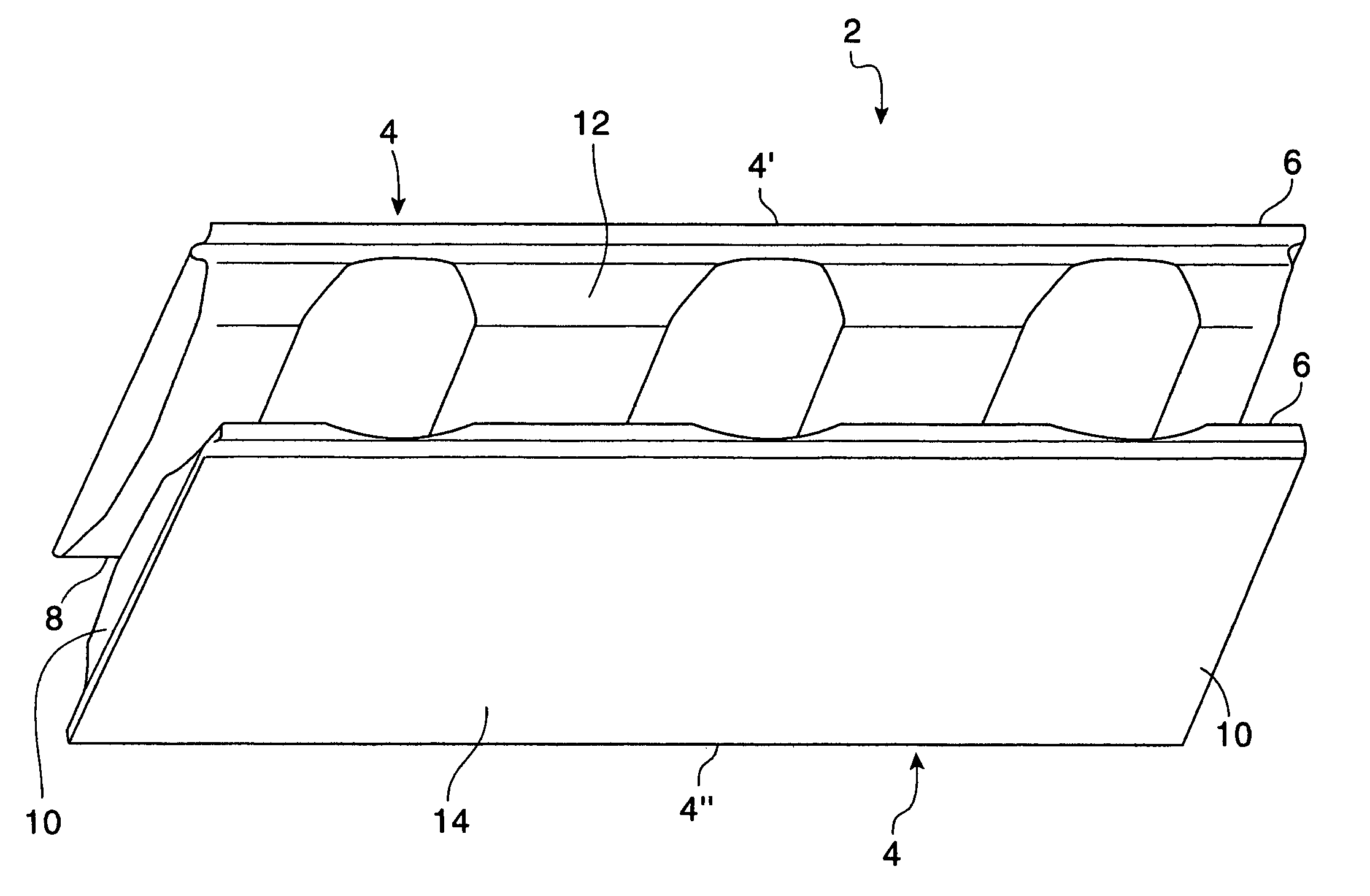
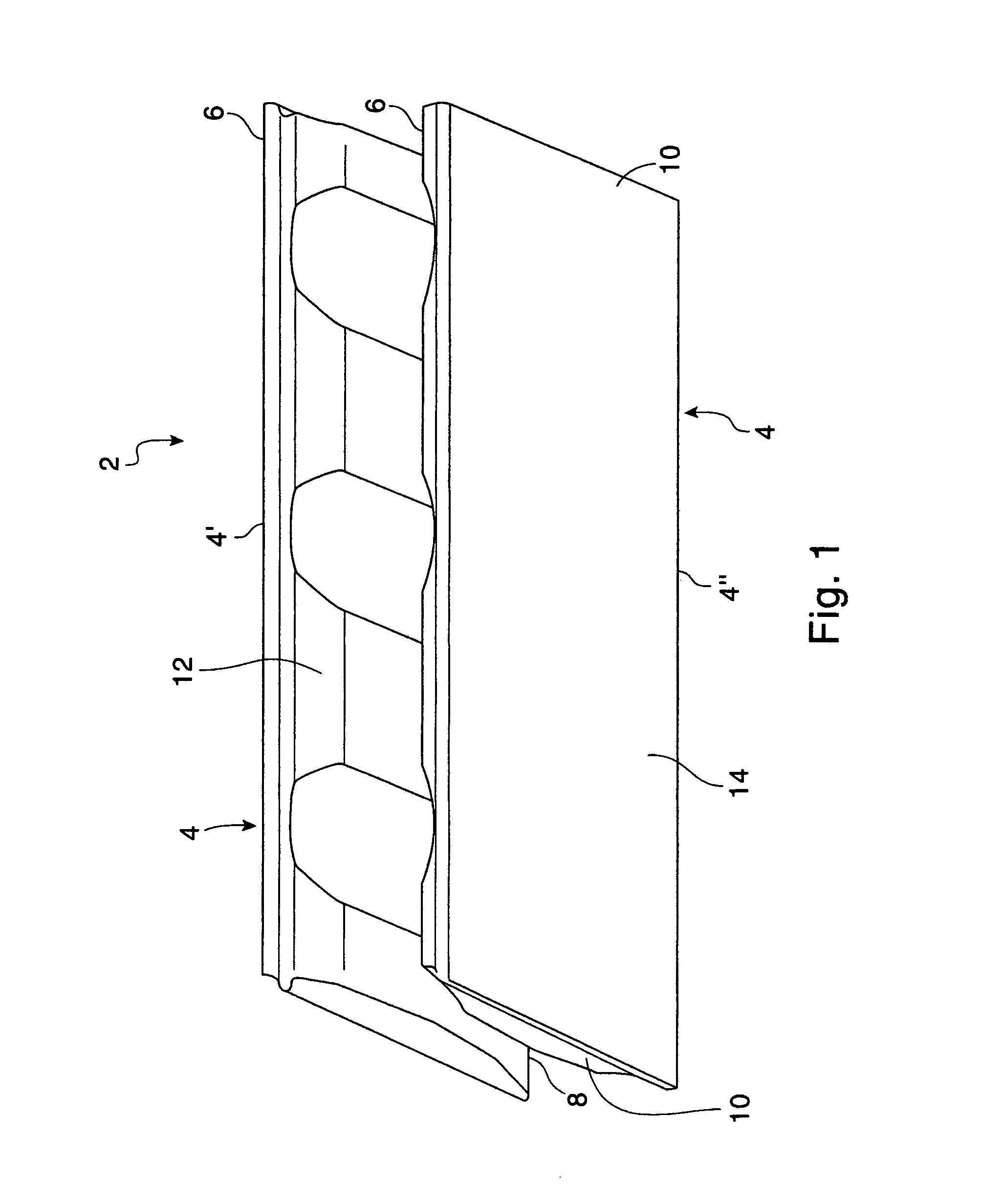
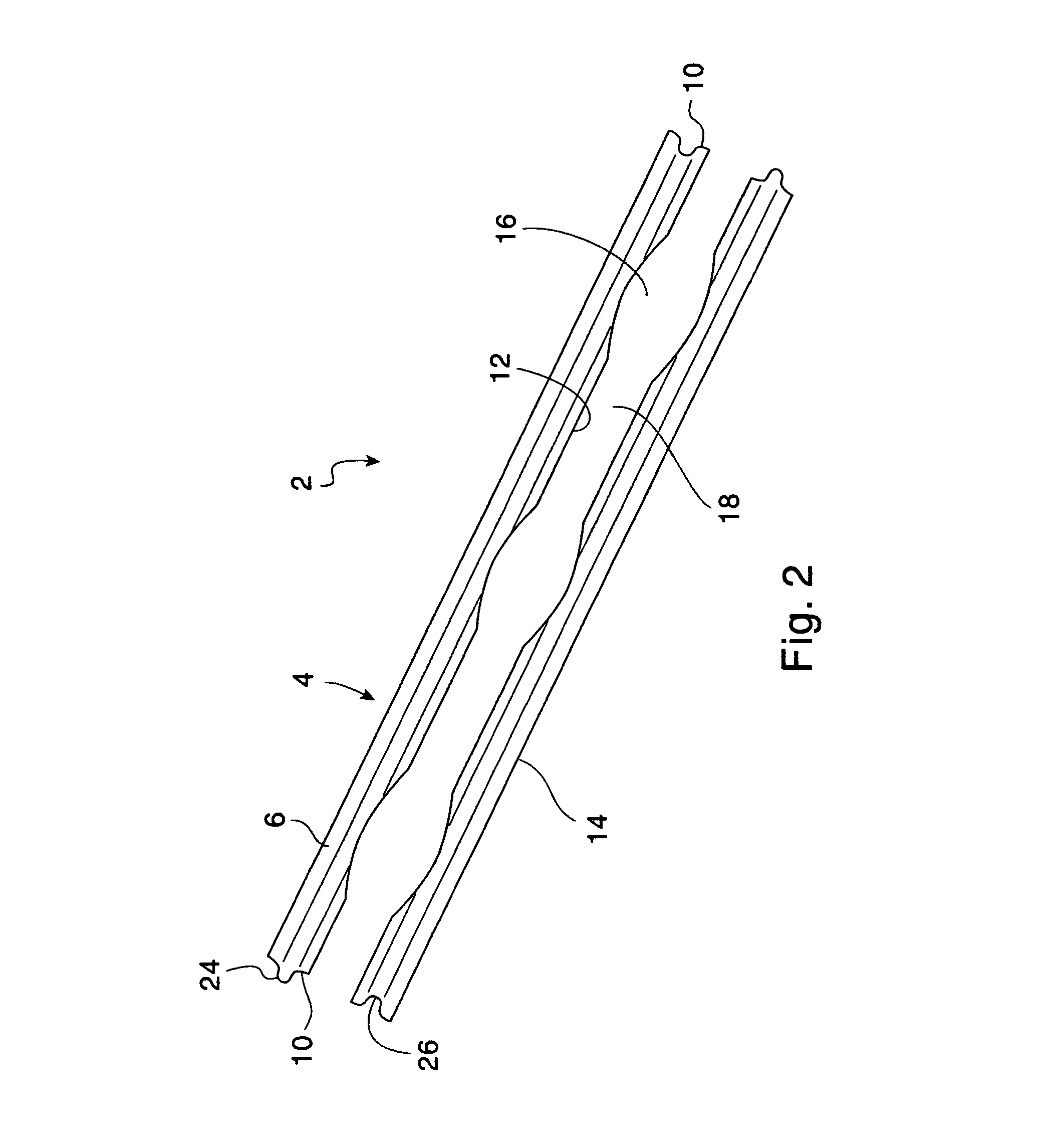
[0076]The invention will now be described with reference to the above drawings wherein like reference numerals refer to like parts throughout the description.

[0077]Turning more particularly to the drawings, FIGS. 1-14, show one type of longitudinal concrete form 2 which comprises a pair of rectangular sidewalls 4. These sidewalls 4 are preferably made of fire-resistant foamed plastic. Each sidewall 4 has upper 6 and lower 8 longitudinal surfaces as well as a pair of opposed vertical surfaces 10. Each sidewall 4 has an inner surface 12 and an outer surface 14. When the longitudinal form 2 is assembled, the inner surfaces 12 of the sidewalls 4 cooperate to form a plurality of vertical cavities 16 and a vertical slot 18. The slot 18 longitudinally spans the length of the form 2 and connects the cavities 16. The outer surface 14 is flat and serves to receive facing or studs.

[0078]As shown best in FIG. 11, each sidewall 4′, 4″ has a raised portion 20 and a non-raised portion 22 along the...


PUM


Abstract

An insulating concrete form foam block bi-directional system comprises a pair of opposed and parallel foam sidewall panels spaced using a plurality of plastic and metal band ties that act as a fire-break between the two exterior finished concrete wall surfaces. Each tie comprises nearly full sidewall height, plastic flanges which engage the sidewalls and a metal band cross-connecting vertical holders of the ties. The metal band forms a wide opening to enhance concrete flow. The tie results in a minimal downward stress impact on the tie during concrete placement. The top and bottom surfaces of each sidewall are formed with raised areas and non-raised areas which interlock with adjacent blocks. The side surfaces of each sidewall are formed with vertical tongues and grooves which interlock with like tongues and grooves of corner pieces which are adapted to form right or left-hand corners.

Description

CROSS-REFERENCE TO RELATED APPLICATIONS[0001](Not applicable)STATEMENT REGARDING FEDERALLY SPONSORED RESEARCH OR DEVELOPMENT[0002](Not applicable)REFERENCE TO SEQUENTIAL LISTING, A TABLE, OR A COMPUTER PROGRAM LISTING APPENDIX SUBMITTED ON A COMPACT DISC[0003](Not applicable)BACKGROUND OF THE INVENTION[0004]1. Field of the Invention[0005]The present invention relates to concrete construction utilizing foam block forms, more specifically to improvements to the foam sidewalls used to create a longitudinally bi-directional system, improved form sidewall spacing ties which create enhanced concrete flow, enhanced strength, and enhanced fire-break properties, and a corner form that can be used as a right-hand or left-hand form.[0006]2. Description of the Related Art[0007]Concrete forms made of a polymeric foam material are known. Such forms basically comprise a pair of laterally spaced-apart sidewalls presenting a cavity therebetween. A number of these forms are connected to present longi...

Claims


Application Information

Patent Timeline
Patent Type & Authority Patents(United States)
IPC IPC(8): E04C1/00E04C3/30E04B1/16E04B2/00E04B1/02
CPCE04B2/8617E04B2002/867
Inventor STOKES, JONATHAN D.
Owner STOKES JONATHAN D
Learn More