
Computer-readable medium, a method and an apparatus for designing and simulating electrodynamic machines implementing conical and cylindrical magnets

a technology of electrodynamic machines and computer-readable media, applied in the field of computer-readable media, can solve the problems of not being able to easily current techniques for designing and simulating conventional motors are not generally well suited to design, and not being able to facilitate the effective development and production of all types of electrodynamic machines. , to achieve the effect of improving one performance characteristic, improving design outcome, and optimizing one or more performance characteristics

Inactive Publication Date: 2013-09-24
REGAL BELOIT AMERICA
View PDF301 Cites 16 Cited by
  • Summary
  • Abstract
  • Description
  • Claims
  • Application Information

AI Technical Summary

Benefits of technology

The patent relates to a way to design and test electric motors and generators using a computer model. The model helps to understand how the motor works and can be used to improve its design. The technical effect of this invention is to provide a better way to create and test new designs for electric machines.

Problems solved by technology

Traditional techniques for designing and simulating conventional motors, while functional, do not readily facilitate the effective development and production of all types of electrodynamic machines.
For example, current techniques for designing and simulating conventional motors are not generally well suited to design and to simulate motors having specific permanent magnet configurations and / or field pole configurations.

Method used


Image

  • Computer-readable medium, a method and an apparatus for designing and simulating electrodynamic machines implementing conical and cylindrical magnets
  • Computer-readable medium, a method and an apparatus for designing and simulating electrodynamic machines implementing conical and cylindrical magnets
  • Computer-readable medium, a method and an apparatus for designing and simulating electrodynamic machines implementing conical and cylindrical magnets

Examples


Embodiment Construction

Definitions

[0019]The following definitions apply to some of the elements described with respect to some embodiments of the invention. These definitions may likewise be expanded upon herein.

[0020]As used herein, the term “air gap” refers to a space, or a gap, between a magnet surface and a confronting pole face. Such a space can be physically described as a volume bounded at least by the areas of the magnet surface and the pole face. An air gap functions to enable relative motion between a rotor and a stator, for example, and to define a flux interaction region. Although an air gap is typically filled with air, it need not be so limiting.

[0021]As used herein, the term “back-iron” commonly describes a physical structure (as well as the materials giving rise to that physical structure) that is often used to complete an otherwise open magnetic circuit. In particular, back-iron structures are generally used only to transfer magnetic flux from one magnetic circuit element to another, such...


PUM


Abstract

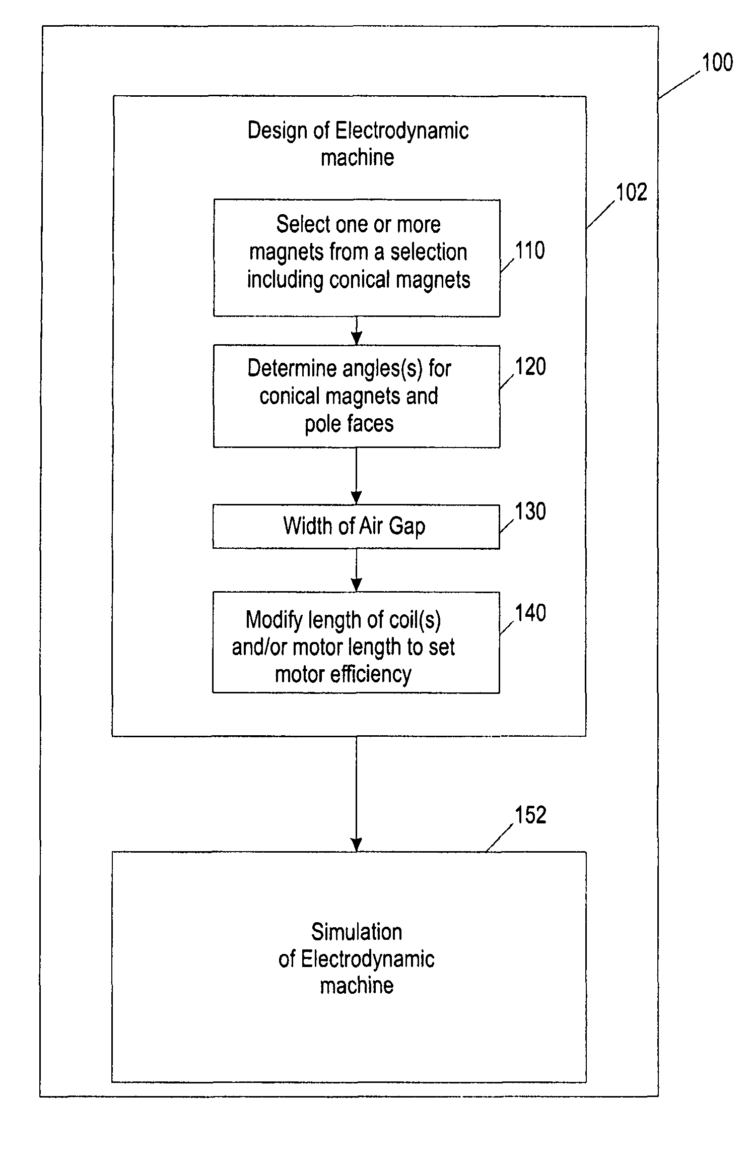
A method, apparatus, system and computer-readable medium for designing and / or simulating electrodynamic machinery are disclosed to, among other things, optimize one or more performance characteristics by manipulating structural and / or functional characteristics of the constituent components of an electrodynamic machine. According to the various embodiments, a motor designer can create a new motor design by modeling a rotor-stator structure to design and / or simulate electrodynamic machines that implement, for example, conically shaped magnets and accompanying field pole members.

Description

CROSS REFERENCE TO RELATED APPLICATION[0001]This application is a Continuation-in-Part of U.S. Nonprovisional application Ser. No. 11 / 255,404, filed on Oct. 20, 2005, which claims priority to U.S. Provisional Application No. 60 / 622,258, filed on Oct. 25, 2004, all of which are herein incorporated by reference. This application also claims the benefit of U.S. Provisional Application No. 60 / 773,750, entitled “Design and Simulation of Electrodynamic Machines Implementing Conical Magnets,” filed on Feb. 14, 2006, the disclosure of which is incorporated by reference. This application also incorporates by reference the following in their entirety: (1.) U.S. Pat. No. 7,061,122 B2, entitled “Rotor-Stator Structure for Electrodynamic Machines,” issued on Jun. 13, 2006, (2.) U.S. Provisional Application No. 60 / 724,055, entitled “Commutation of Brushless Electrodynamic Machines,” and filed on Oct. 5, 2005; (3.) U.S. Provisional Application No. 60 / 773,500, entitled “Field Pole Member for Electr...

Claims


Application Information

Patent Timeline
IPC IPC(8): G06G7/62G06F17/50
CPCH02K21/12H02K1/14H02K16/00H02K2201/03H02K2213/03H02K2201/06H02K2201/12Y02T10/82
Inventor PETRO, JOHN PATRICKWASSON, KEN GEORGE
Owner REGAL BELOIT AMERICA
Learn More