
Multi-wavelength optical transmitting and receiving modules

a multi-wavelength, receiving module technology, applied in the direction of optics, instruments, optical light guides, etc., can solve the problems of large loss of optical signals, difficult to design electrical signal interfaces and reduce the size of optical transmitting and receiving modules, and related optical loss, so as to achieve easy alignment, high production yield, and high tolerance for alignment

Active Publication Date: 2013-09-24
ELECTRONICS & TELECOMM RES INST
View PDF17 Cites 59 Cited by
  • Summary
  • Abstract
  • Description
  • Claims
  • Application Information

AI Technical Summary

Benefits of technology

The patent is about creating optical modules that can transmit and receive light of different wavelengths. These modules have several benefits including being tolerant to channel alignment, easy to align, and having high production yields and mass productivity.

Problems solved by technology

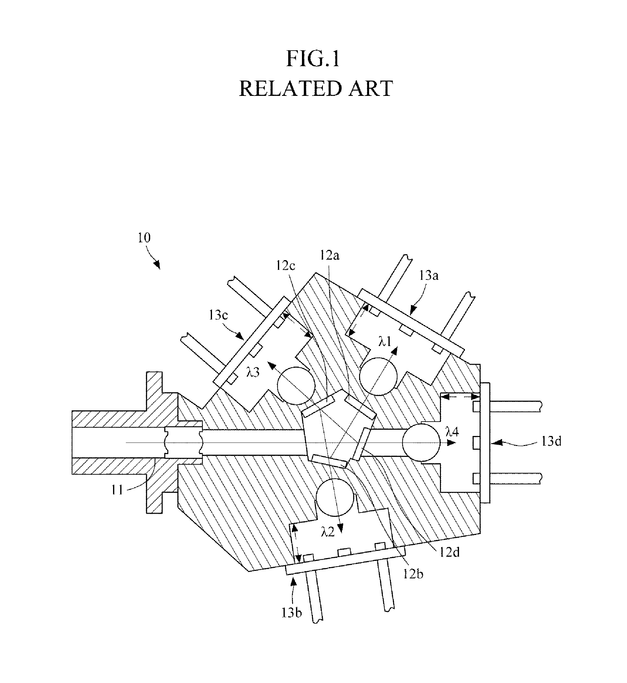
Thus, it may be very difficult to design an electrical signal interface and reduce the size of the optical transmitting and receiving module 10.
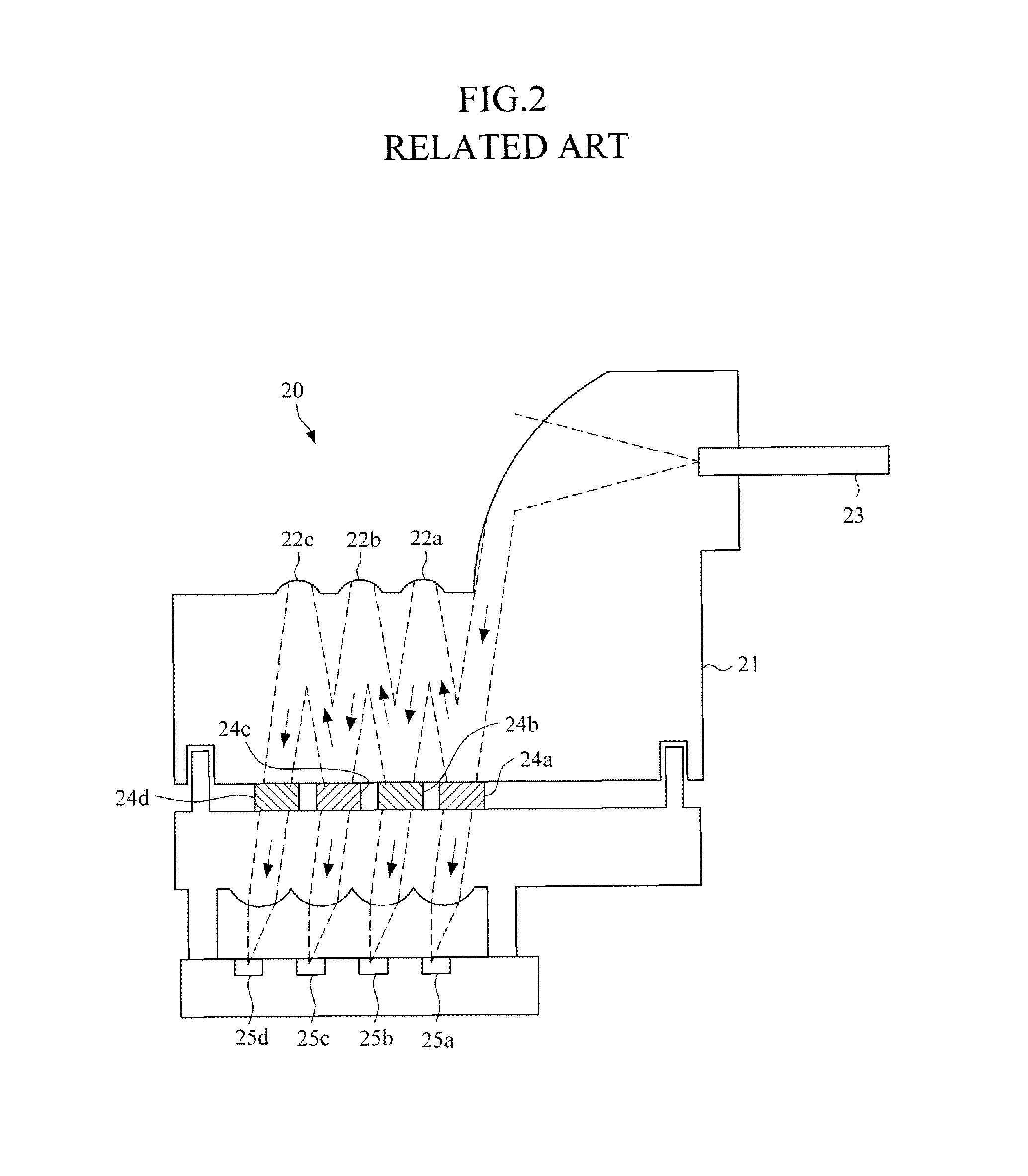
Thus, the presence of a manufacturing error in the optical transmitting and receiving module 20 may result in a large loss of optical signals.
In addition, since the optical transmitting and receiving module 20 using the relay mirrors 22a through 22c has a lower alignment tolerance than an optical transmitting and receiving module using lenses, a significant alignment-related optical loss may occur, thereby deteriorating mass productivity.

Method used


Image

  • Multi-wavelength optical transmitting and receiving modules
  • Multi-wavelength optical transmitting and receiving modules
  • Multi-wavelength optical transmitting and receiving modules

Examples


Embodiment Construction

[0031]The above and other features and advantages of the present invention will become more apparent by describing exemplary embodiments thereof with reference to the attached drawings.

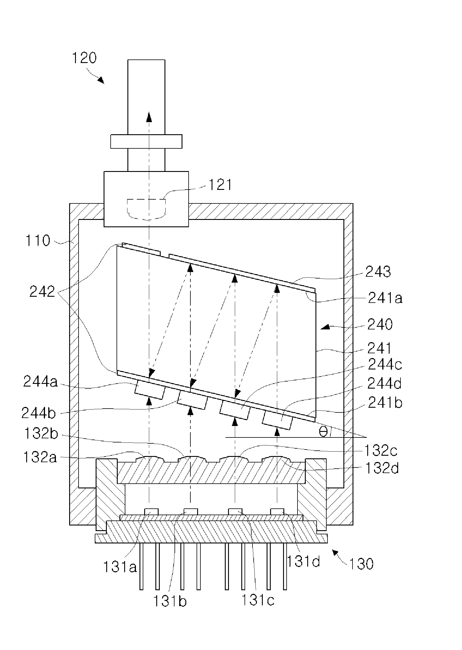
[0032]FIG. 3 is a cross-sectional view of an exemplary multi-wavelength optical transmitting module 100. Referring to FIG. 3, the multi-wavelength optical transmitting module 100 includes a housing 110, an optical output block 120, an optical transmitting block 130, and an optical multiplexer (MUX) block 140.

[0033]The housing 110 includes space therein, and a first coupling hole 111 and a second coupling hole 112 are respectively formed in opposite surfaces of the housing 110. The optical output block 120 is coupled to the first coupling hole 111, and the optical transmitting block 130 is coupled to the second coupling hole 112. The first and second coupling holes 111 and 112 may be large enough to respectively allow the optical output block 120 and the optical transmitting block 130 to be partially i...


PUM


Abstract

A multi-wavelength optical transmitting module includes a housing, an optical output block, an optical transmitting block, and an optical multiplexer (MUX) block. The optical output block is coupled to a first coupling hole of the housing and to an optical signal connector, and includes a first lens. The optical transmitting block is coupled to a second coupling hole of the housing and to an electrical signal connector. The optical transmitting block includes a plurality of transmitting devices which respectively output light having different wavelengths and are arranged parallel to the optical output block, and a plurality of second lenses which correspond respectively to the transmitting devices. The optical multiplexer (MUX) block multiplexes optical signals of multiple wavelengths, which were output from the transmitting devices and passed through the second lenses, and transmits the multiplexed optical signals to the optical output block.

Description

CROSS REFERENCE TO RELATED APPLICATION[0001]This application claims the benefit under 35 U.S.C. §119(a) of Korean Patent Applications No. 10-2009-84153, filed on Sep. 7, 2009 and No. 10-2009-116985, filed on Nov. 30, 2009, the disclosures of which are incorporated by reference in its entirety for all purposes.BACKGROUND[0002]1. Field[0003]The following description relates to multi-wavelength optical transmitting and receiving modules which can be used to multiplex and demultiplex optical signals of multiple wavelengths.[0004]2. Description of the Related Art[0005]An increase in data traffic resulting from the advancement of the Internet is increasing the speed and volume of optical communication networks. For transmission of high-volume data traffic, wavelength division multiplexing (WDM) is widely used. WDM is a technology that multiplexes optical signals having different wavelengths on a single optical fiber. WDM has been used mainly in backbone networks but has also been applied ...

Claims


Application Information

Patent Timeline
Patent Type & Authority Patents(United States)
IPC IPC(8): G02B6/36G02B6/32
CPCG02B6/4215G02B6/12009G02B6/29367G02B6/32
Inventor LEE, JOON KIKANG, SAE-KYOUNG
Owner ELECTRONICS & TELECOMM RES INST
Learn More