
Apparatus and method for anchor bolt grouting

a technology of anchor bolt and filling apparatus, which is applied in the direction of packaging foodstuffs, instruments, packaged goods, etc., can solve the problems of inability to color resin mastic, inability to use dual pumping systems, and high initial setup and maintenance costs of resin mastic made with a lower cost gray ground calcium carbonate, etc., to achieve low cost and low cost. , the effect of cost saving

Inactive Publication Date: 2013-09-24
FCI HLDG DELAWARE
View PDF31 Cites 3 Cited by
  • Summary
  • Abstract
  • Description
  • Claims
  • Application Information

AI Technical Summary

Benefits of technology

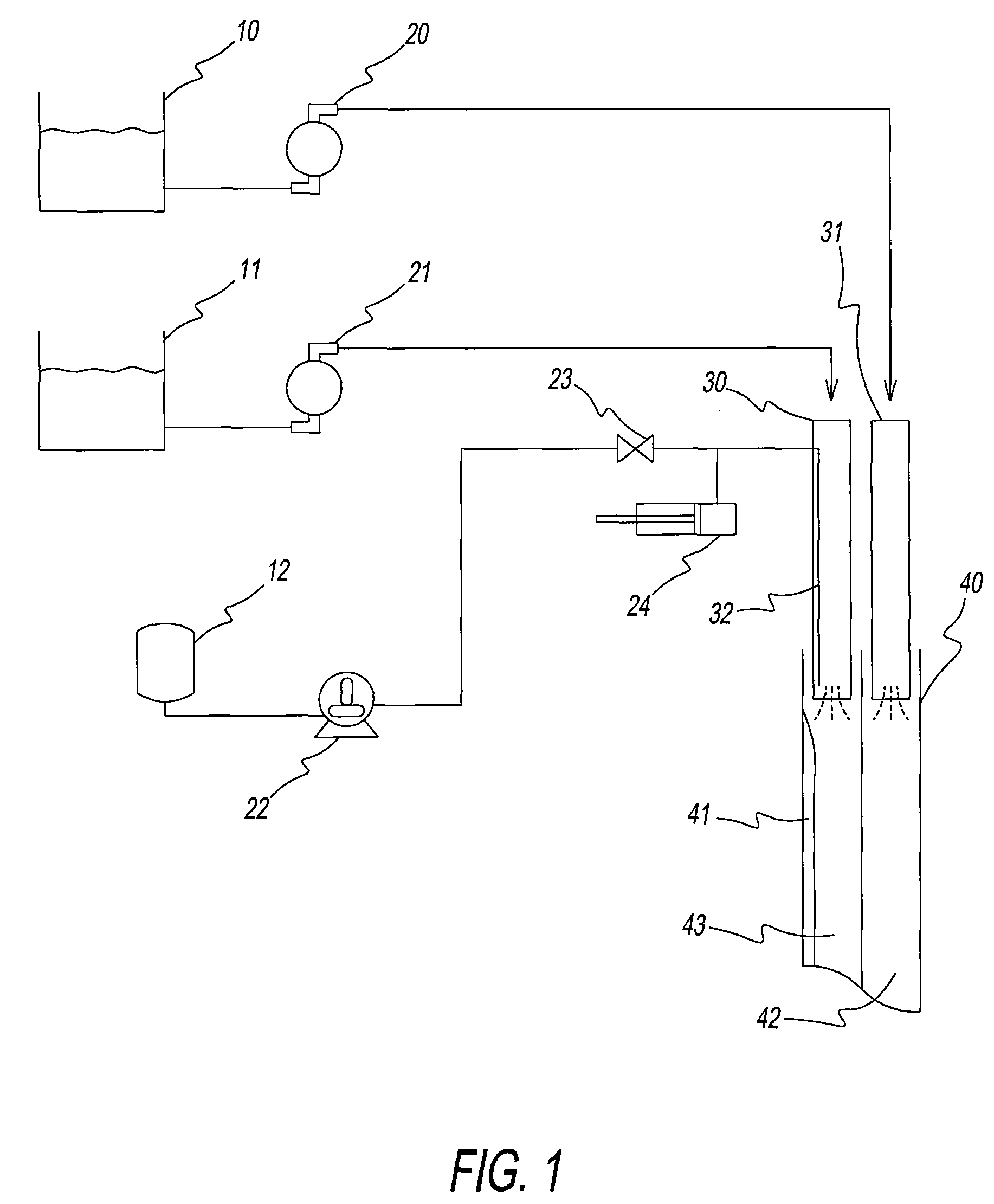
This patent is about a low-cost cartridge that can be used for two different gel times. The cartridge is designed to clearly show which end has the slower gel time to prevent incorrect installation in a mine. The filling system is cost-effective because it requires only one resin pump for both fast and slow resin mastic. The use of a low-cost method for injecting the resin mastic and a vacuum system allows for the use of a lower-cost filler. The technical effects of this patent are a more affordable and efficient method for designing and filling cartridges for different resin mastics.

Problems solved by technology

It is sometimes advantageous to the rock reinforcement to apply a tension load to a bolt after it is installed.
For example, two-speed resin cartridges are conventionally produced by making two resin mastics at different gel times and then using an alternating pumping system that switches the resin feed to the cartridge fill tube back and forth between the resin mastics of two different gel times. The disadvantage to the conventional method is the resin mastic is difficult to pump and a dual pumping system is expensive for initial setup and maintenance.
Resin mastic made with a lower cost gray ground calcium carbonate cannot be colored due to the black influence of impurities in the calcium carbonate.

Method used


Image

  • Apparatus and method for anchor bolt grouting
  • Apparatus and method for anchor bolt grouting
  • Apparatus and method for anchor bolt grouting

Examples


examples

[0075]Lab work was done to determine inhibitor amounts to adjust a fast resin mastic gel time to a slow resin mastic gel time. A batch of resin mastic with a gel time of 10 to 14 sec and 84 to 87% filler was used for the experiment. Table 1 shows the amount of inhibitor hand mixed into the resin mastic and the corresponding gel time results. The relationship of amount of inhibitor to corresponding gel times appears to be close to linear.

[0076]

TABLE 1% Inhibitor to resin mastic0.0075%0.0150%0.0300%.0450%.0500%Gel time in sec32.650.069.094.0108.0with Hydro-quinone (HQ)Gel time in sec28.246.462.082.0with Toluhydro-quinone (THQ)

[0077]A highly visible pigment dispersion was found to provide a method to make the inhibitor solution visible in the resin cartridge. The pigment dispersion had to be miscible with the inhibitor solution. Experiments for phase separation were run with 50 / 50 mixtures of inhibitor solutions and pigment dispersions in glycol, plasticizer, and polyester. A pigment d...


PUM

PropertyMeasurementUnit
widthaaaaaaaaaa
depthaaaaaaaaaa
lengthsaaaaaaaaaa

Abstract

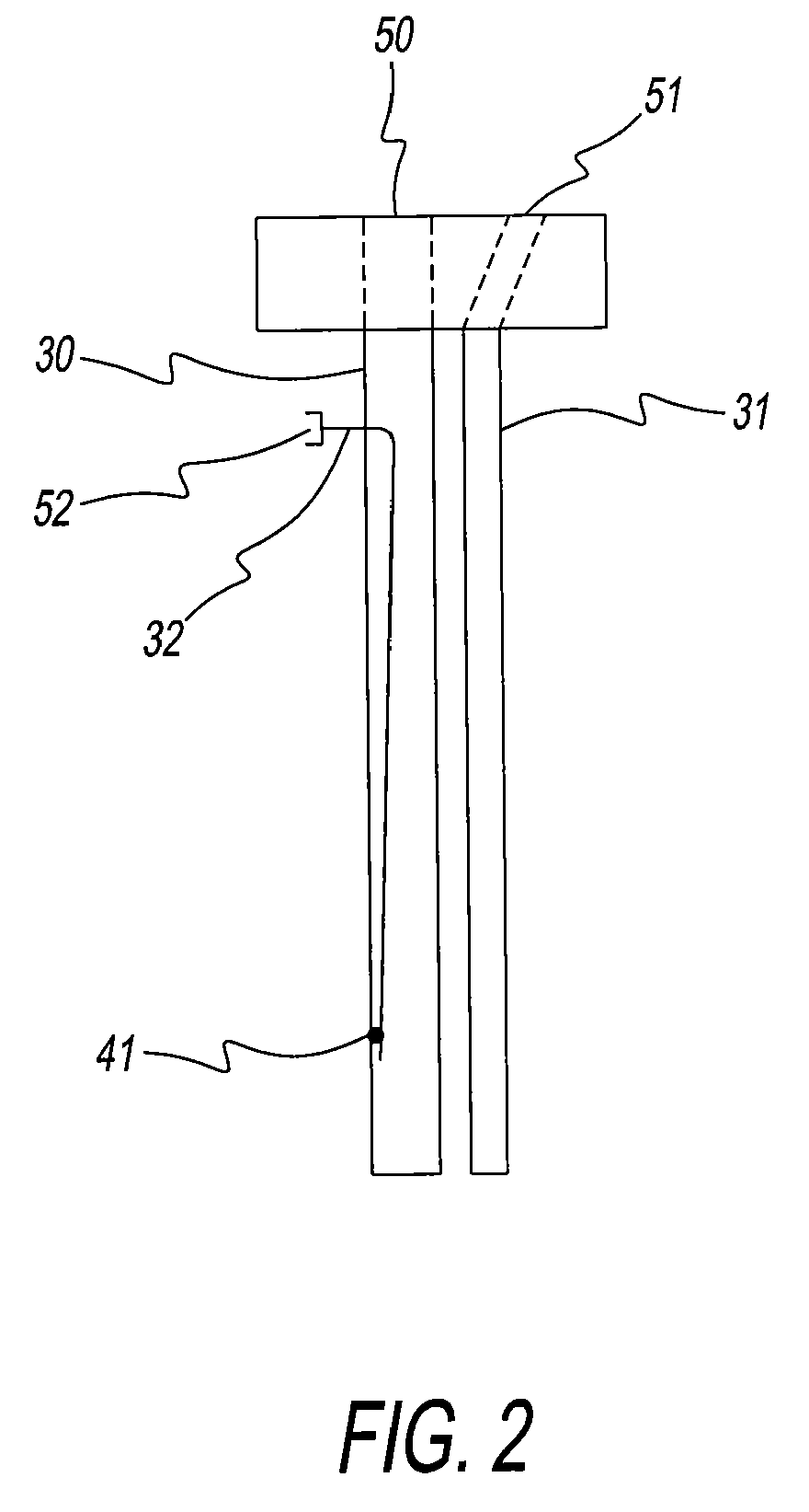
A filling apparatus for a grouting system. The filling apparatus comprises a first fill tube and a second fill tube. The first fill tube is discrete from the second fill tube. The first fill tube is disposed for transporting resin mastic and the second fill tube is disposed for transporting initiator. A portion of the first fill tube has an inlet opening through which an injection quill extends interiorly and downwardly through the first fill tube. The injection quill is disposed for transporting inhibitor. This disclosure also relates to a method for adjusting gel time of a grouting system used for anchoring a reinforcing member in an opening, a grouting system for anchoring a reinforcing member in an opening, and a method for anchoring a reinforcing member in a mine.

Description

BACKGROUND[0001]1. Field of the Disclosure[0002]This disclosure relates to a filling apparatus for a grouting system, a method for adjusting gel time of a grouting system used for anchoring a reinforcing member, e.g., bolts and other supports, in a mine, a grouting system for anchoring a reinforcing member in a mine, and a method of anchoring a reinforcing member in a mine.[0003]2. Discussion of the Background Art[0004]Anchor bolts are employed in various fields of engineering, for example, as strengthening or reinforcing members in rock formations and in structural bodies. The bolts are inserted into drill holes in the formation or body, and often are fixed or anchored, at their inner end or over substantially their entire length, by means of a reactive chemical grouting composition that hardens around the bolt. When used in a mine roof, bolts grouted in this manner help significantly to prevent mine roof failure.[0005]A chemical anchor grouting composition can contain a polyester ...

Claims


Application Information

Patent Timeline
Patent Type & Authority Patents(United States)
IPC IPC(8): B65B1/04B65B39/00
CPCB65B29/10E21D20/026E21D20/028F16B13/142F16B13/146B65B39/00E21F17/00B65B2220/14
Inventor JONES, ROY CARLTONGRAMLICH, JR., PHILLIP EDWIN
Owner FCI HLDG DELAWARE
Learn More