
Reception apparatus, reception method, reception program, and reception system

a technology for reception apparatuses and programs, applied in multi-frequency code systems, digital transmission, amplitude demodulation, etc., can solve problems such as the inability of reception apparatuses to correctly demodulate dvb-t2 signals and the inability of reception apparatuses to acquire information necessary for frame demodulation

Active Publication Date: 2013-09-17
SATURN LICENSING LLC
View PDF4 Cites 8 Cited by
  • Summary
  • Abstract
  • Description
  • Claims
  • Application Information

AI Technical Summary

Benefits of technology

Enables correct demodulation of DVB-T2 signals even in the presence of spectrum inversion, ensuring accurate acquisition of information for frame demodulation and proper signal processing.

Problems solved by technology

In such a case, the reception apparatus cannot demodulate the DVB-T2 signal correctly.
When the P1 signal is not correctly demodulated, the reception apparatus cannot acquire information necessary for frame demodulation.

Method used


Image

  • Reception apparatus, reception method, reception program, and reception system
  • Reception apparatus, reception method, reception program, and reception system
  • Reception apparatus, reception method, reception program, and reception system

Examples


first embodiment

[Configuration Example of the Reception System as the First Embodiment]

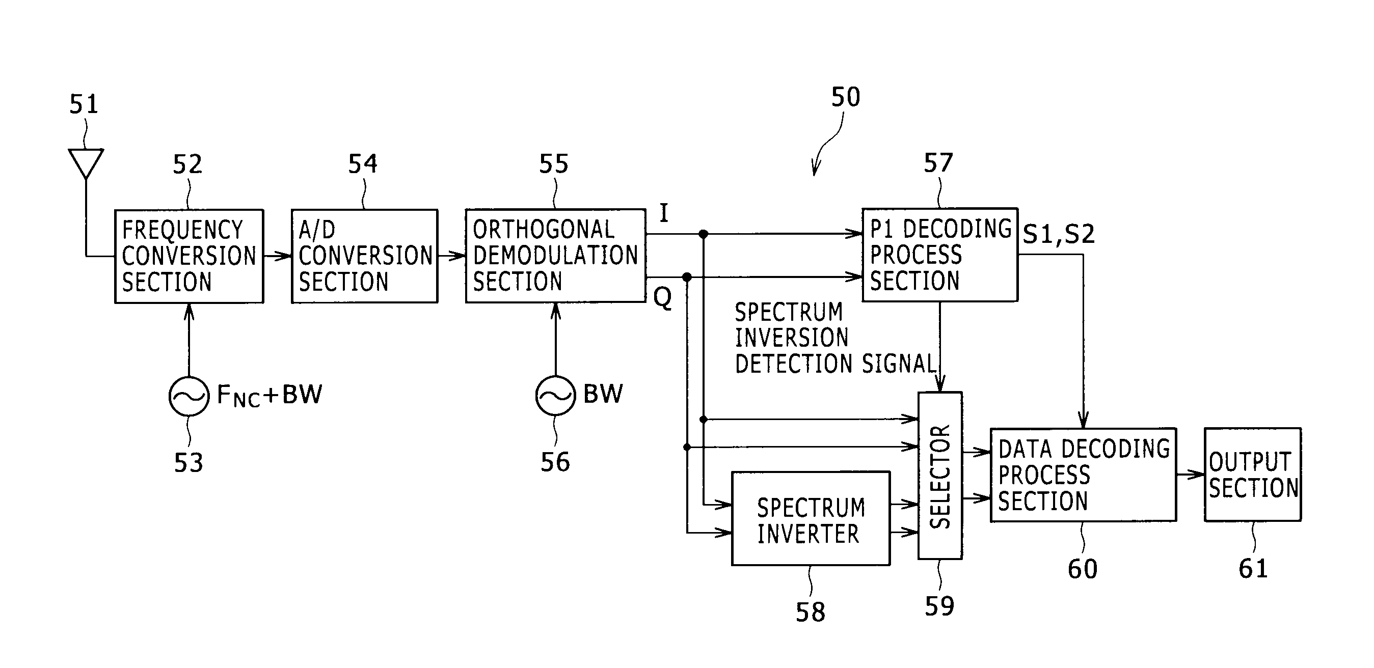
[0063]FIG. 5 is a block diagram showing a configuration example of a reception system as the first embodiment of the present invention.

[0064]The reception system 50 in FIG. 5 is made up of an antenna 51, a frequency conversion section 52, a local oscillator 53, an A / D conversion section 54, an orthogonal demodulation section 55, a local oscillator 56, a P1 decoding process section 57, a spectrum inverter 58, a selector 59, a data decoding process section 60, and an output section 61.

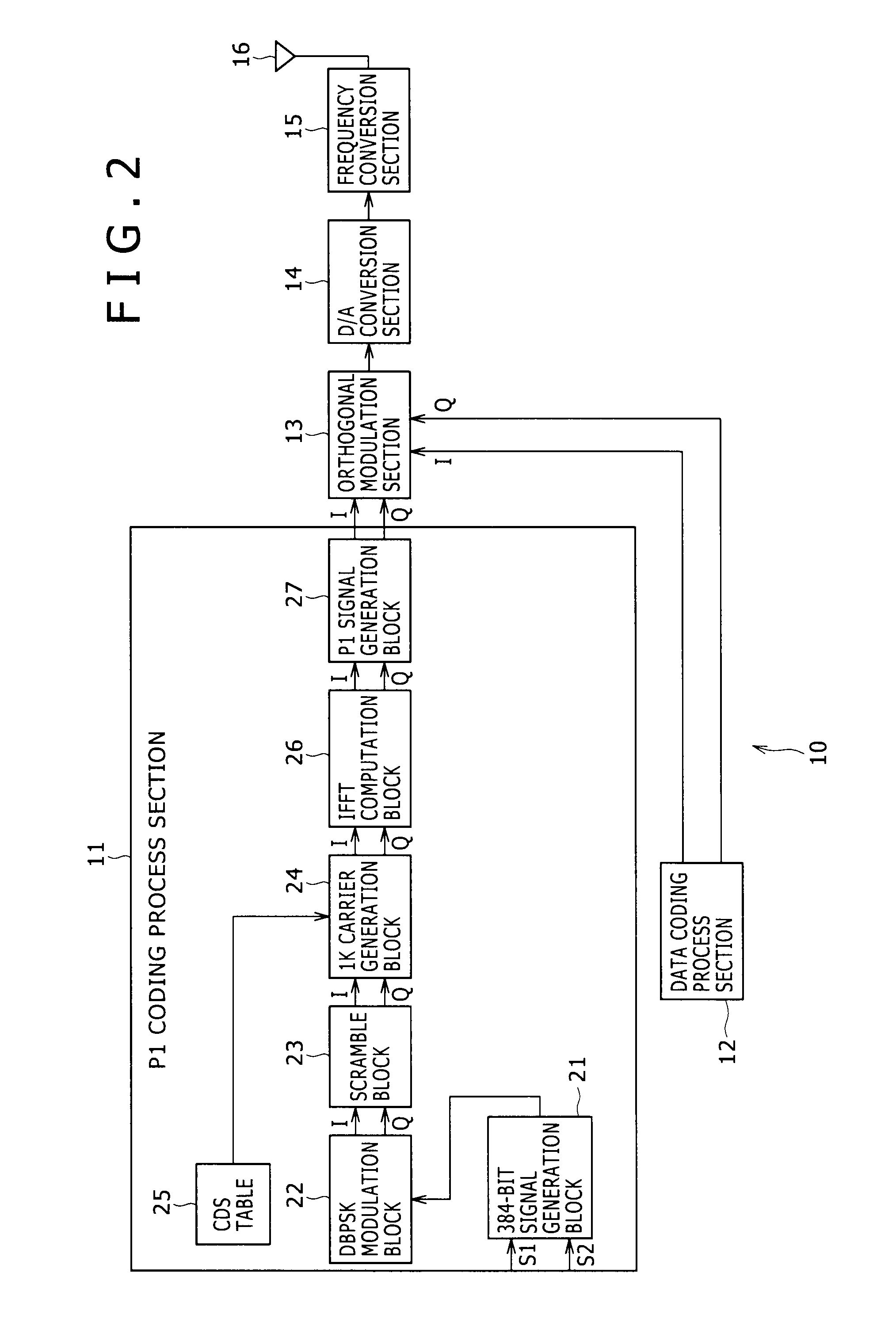
[0065]The antenna 51 acquires the RF signal out of the DVB-T2 signal sent from the transmission system 10 in FIG. 2. The RF signal thus acquired is fed to the frequency conversion section 52.

[0066]The frequency conversion section 52 multiplies the RF signal coming from the antenna 51 by a carrier having an oscillation frequency of (FNC+BW) supplied by the local oscillator 53, thereby converting the RF signal into an IF signal having t...

third embodiment

[Configuration Example of the Reception System as the Third Embodiment]

[0226]FIG. 22 is a block diagram showing a configuration example of a reception system as the third embodiment of the present invention.

[0227]Of the components making up the configuration in FIG. 22, those also found in FIG. 5 are designated by like reference numerals, and their descriptions will be omitted hereunder where redundant.

[0228]The configuration of the reception system 290 in FIG. 22 is substantially the same as the configuration in FIG. 5 except that a recording control section 291 and a recording section 292 are installed to replace the output section 61. The reception system 290 records broadcast signals without outputting images or sounds corresponding to the signals.

[0229]More specifically, the recording control section 291 causes the recording section 292 to record the broadcast signal output from the data decoding process section 60. The recording section 292 is composed of a hard disk or of rem...


PUM


Abstract

Disclosed herein is a reception apparatus including: a spectrum inversion detection section configured to detect the occurrence or absence of spectrum inversion in a received signal complying with the Digital Video Broadcasting-Terrestrial 2 standard known as DVB-T2, using a P1 signal constituting the received signal; a spectrum inversion section configured to perform a spectrum inversion process on the received signal if the occurrence of the spectrum inversion is detected at least by the spectrum inversion detection section; and a demodulation section configured to demodulate the received signal having undergone the spectrum inversion process if the occurrence of the spectrum inversion is detected by the spectrum inversion detection section, the demodulation section further demodulating the received signal yet to undergo the spectrum inversion process if the absence of the spectrum inversion is detected by the spectrum inversion detection section.

Description

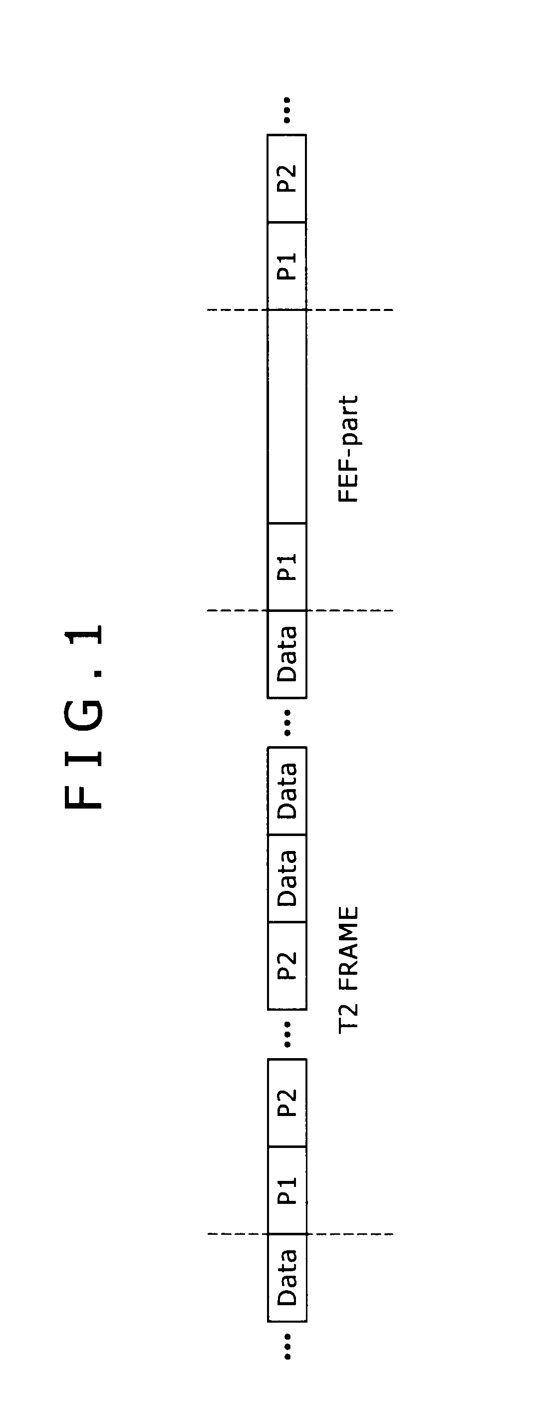
BACKGROUND OF THE INVENTION[0001]1. Field of the Invention[0002]The present invention relates to a reception apparatus, a reception method, a reception program, and a reception system. More particularly, the invention relates to a reception apparatus, a reception method, a reception program, and a reception system whereby signals received in compliance with the DVB-T2 (Digital Video Broadcasting-Terrestrial 2) standard can be demodulated correctly even if spectrum inversion occurs.[0003]2. Description of the Related Art[0004]The DVB-T2 standard is currently worked out as a representative standard for terrestrial digital broadcasting (see “Frame structure channel coding and modulation for a second-generation digital terrestrial television broadcasting system (DVB-T2),” a DVB website updated on Jun. 30, 2008; searched for on May 27, 2009 on the Internet at <URL=http: / / www.dvb.org / technology / dvbt2 / a122.tm3980r5.DVB-T2.pdf>). Terrestrial digital broadcasts based on the DVB-T2 stan...

Claims


Application Information

Patent Timeline
Patent Type & Authority Patents(United States)
IPC IPC(8): H04L27/06
CPCH04L27/2647H04L27/2657
Inventor KAWAUCHI, HIDETOSHIYOKOKAWA, TAKASHI
Owner SATURN LICENSING LLC
Learn More