
Adaptive robotic gripper

a robotic gripper and adaptive technology, applied in the field of robots, can solve the problems of compounding difficulty, complex design problem of devices, and difficult design challeng

Active Publication Date: 2013-09-17
HARRIS CORP
View PDF36 Cites 48 Cited by
  • Summary
  • Abstract
  • Description
  • Claims
  • Application Information

AI Technical Summary

Benefits of technology

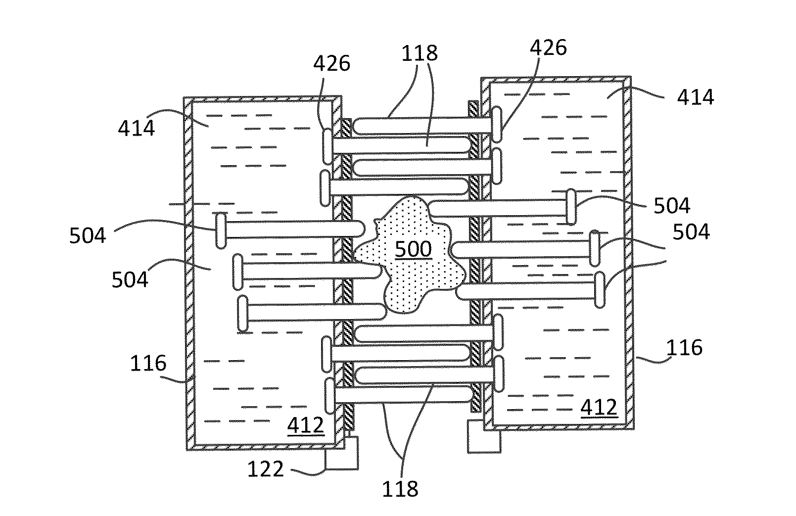
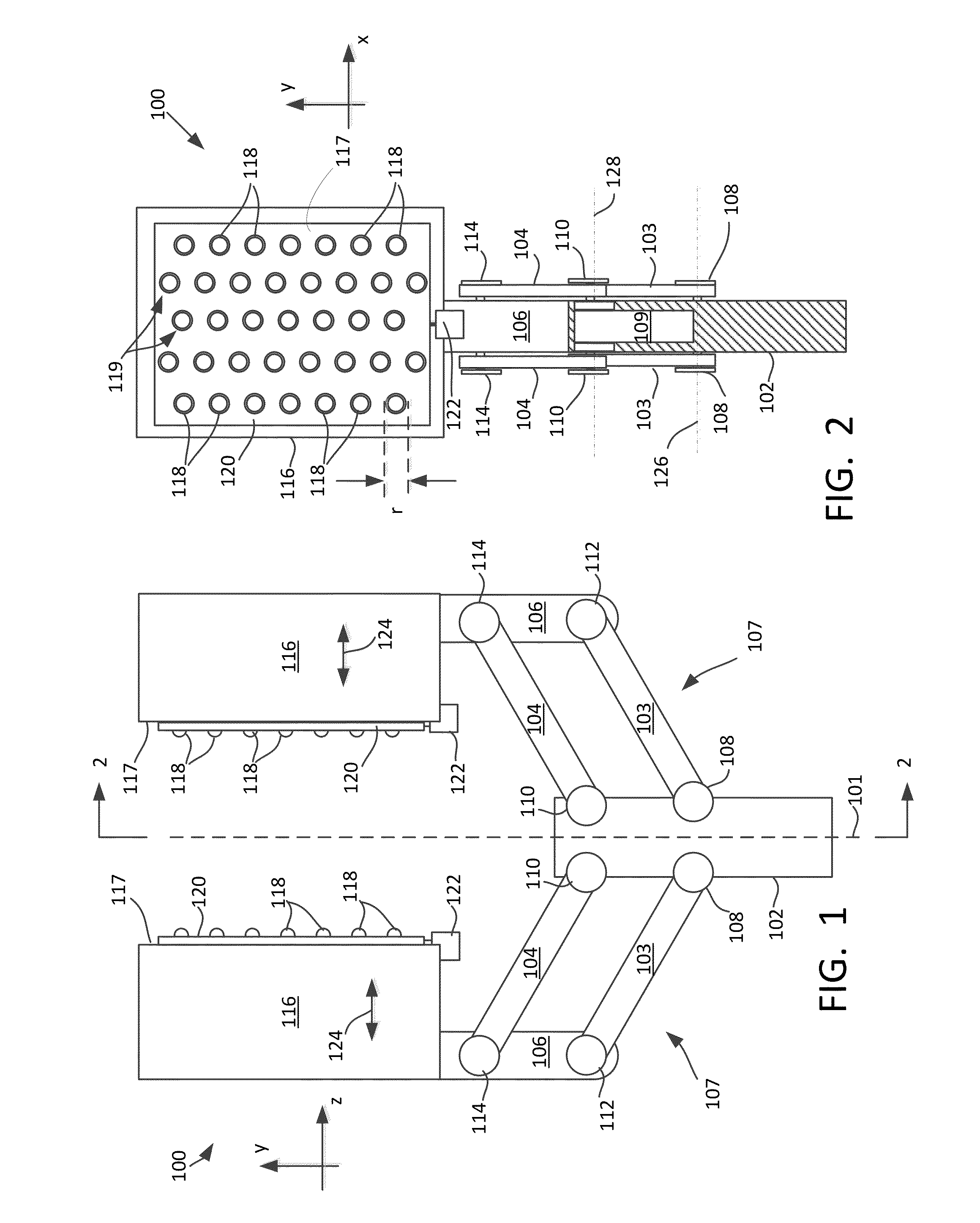
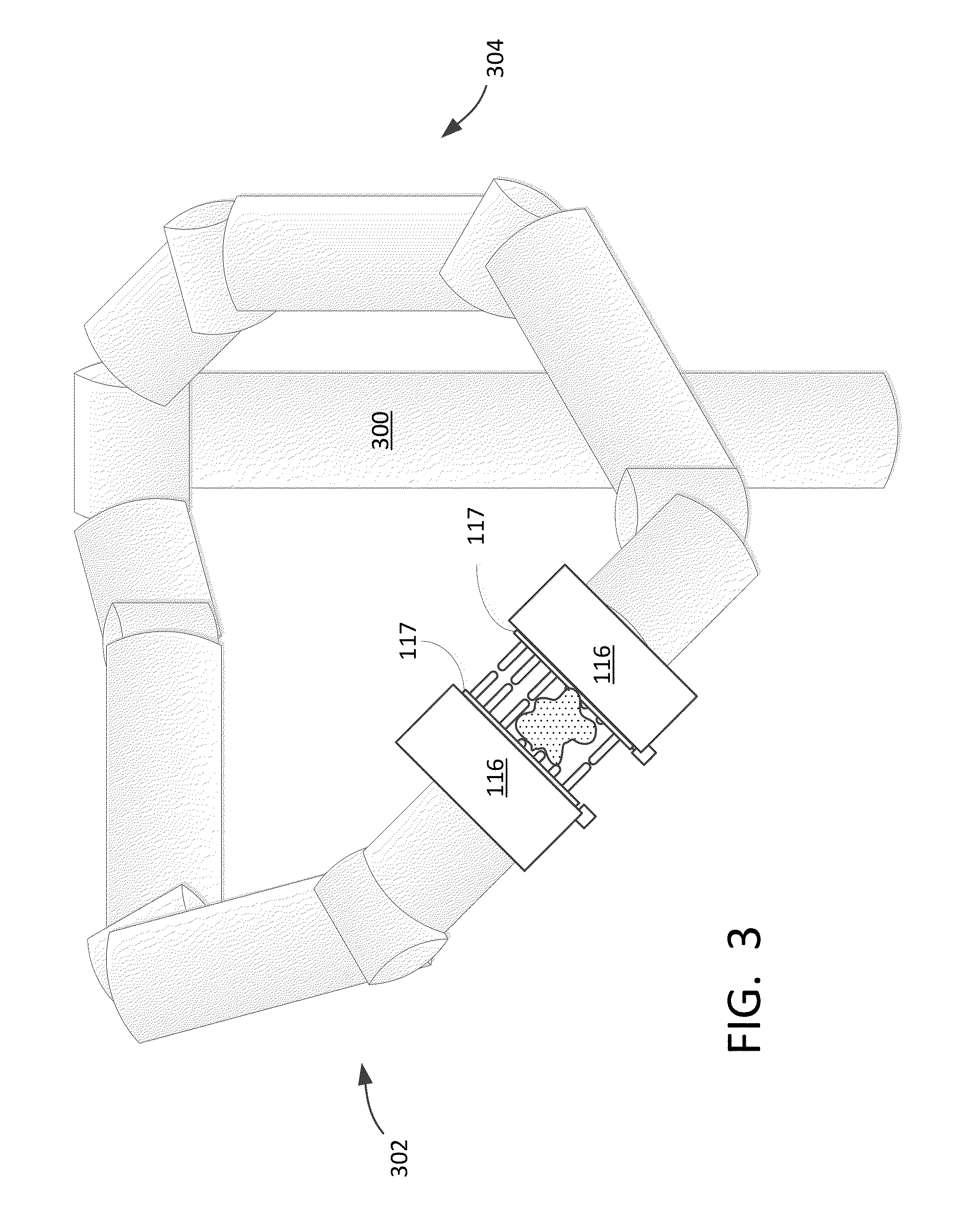
The invention provides a method and system for grasping objects using two gripping pads that can be moved to different locations. Pins are extended from the gripping pads to form a gripping contour that matches the shape of the object being grasped. The method allows for independent control of each pin, resulting in greater efficiency and stability during the grasping process. The system includes a control system and a mechanical linkage to move the gripping pads, as well as a fluid system to extend the pins and determine their extension distance independently. The technical effects of this invention include improved efficiency, stability, and flexibility in the grasping process.

Problems solved by technology

Systems for grasping well known objects, or a limited number of object types, present a relatively straightforward design problem because a gripper design can be selected that is well suited to the particular task.
The design problem can be more complex with regard to devices which are expected to grasp a wider variety of objects of arbitrary shape.
The absence of a priori knowledge regarding the type of object, variation in object type, variable / unknown object location and / or variable object pose can present a difficult design challenge.
This difficulty is compounded by the additional need for a grasping device to have a design which is simple, robust and tolerant of poor or inaccurate sensor information.
However, these types of grasping devices often require complex grasp planning and a good knowledge of the grasped object.
Also, grasping devices with fully or partially articulated fingers can often require many actuators.
The complexity and number of actuators tend to make such devices expensive and prone to mechanical failure.
However, they require the gripping pad to be pushed onto objects with significant force.
Also, the pliable outer membrane is prone to being punctured or wearing out.

Method used


Image

  • Adaptive robotic gripper
  • Adaptive robotic gripper
  • Adaptive robotic gripper

Examples


Embodiment Construction

[0019]The invention is described with reference to the attached figures. The figures are not drawn to scale and they are provided merely to illustrate the instant invention. Several aspects of the invention are described below with reference to example applications for illustration. It should be understood that numerous specific details, relationships, and methods are set forth to provide a full understanding of the invention. One having ordinary skill in the relevant art, however, will readily recognize that the invention can be practiced without one or more of the specific details or with other methods. In other instances, well-known structures or operation are not shown in detail to avoid obscuring the invention. The invention is not limited by the illustrated ordering of acts or events, as some acts may occur in different orders and / or concurrently with other acts or events. Furthermore, not all illustrated acts or events are required to implement a methodology in accordance wit...


PUM


Abstract

A method for grasping an object includes moving a first and second gripping pad (116) respectively to first and second locations in which a first face (117) of the first gripping pad is opposed from a second face (117) of the second gripping pad and spaced apart a distance. Two or more of pins (118) included in each gripping pad are extended from at least the first face in a direction toward the second face. Thereafter, an extension distance for each of the pins is independently determined responsive to a resistance encountered by each of the pins as a result of the extending. As a result of the independently determining step, an object-defined gripping contour is provided as formed by distal ends of the pins.

Description

BACKGROUND OF THE INVENTION[0001]1. Statement of the Technical Field[0002]The inventive arrangements relate to robotics and more particularly to robotic methods and systems for grasping objects.[0003]2. Description of the Related Art[0004]Systems involving robotics and telematics frequently include some means by which a machine can grasp and manipulate objects. Systems for grasping well known objects, or a limited number of object types, present a relatively straightforward design problem because a gripper design can be selected that is well suited to the particular task. Such grasping problems can be addressed with relative ease using conventional structured grasping methods. For example, grasping devices in such scenarios can have two or three solid fingers with simple geometry (flat surfaces). Alternatively, the fingers used in such simple grasping devices can have a geometry that includes a customized surface which is particularly effective for grasping objects having a specific...

Claims


Application Information

Patent Timeline
IPC IPC(8): B25J15/10
CPCB25J15/10B25J15/106
Inventor BOSSCHER, PAUL M.SUMMER, MATTHEW D.
Owner HARRIS CORP
Learn More