
Combined heating and air conditioning system for vehicles

a technology for air conditioning systems and vehicles, applied in refrigeration machines, light and heating equipment, transportation and packaging, etc., can solve the problems of wasting money, the cooling system cannot cool the passenger compartment, and the engine is turned off, so as to increase the efficiency of heating mode

Active Publication Date: 2013-08-27
BERGSTROM INC
View PDF161 Cites 59 Cited by
  • Summary
  • Abstract
  • Description
  • Claims
  • Application Information

AI Technical Summary

Benefits of technology

Enables efficient heating and cooling of vehicle compartments without engine operation, reducing energy waste and pollution, while minimizing the likelihood of refrigerant leaks and system complexity.

Problems solved by technology

Unfortunately, this requires the engine to be running or turned on and off to heat the passenger compartment.
While these engine-belt driven compressors are well-suited to circulate and pump refrigerant through the refrigerant system while the engine is running, they are not able to operate when the engine is turned off.
As a result, the cooling system cannot cool the passenger compartment unless the engine of the bus is left running.
Unfortunately, leaving the engine running simply to condition the air in the passenger compartment wastes money and increases the pollution produced over the life of the bus.
Unfortunately, while in the engine off condition, some no-idle systems are not capable of providing both heating as well as cooling in an engine off condition using a single circuit.
Unfortunately, this increases the amount of space required for the entire HVAC system.
Another problem with standard cooling systems that these high pressure refrigerant systems use couplings which makes the system prone to leaks.
Further, because the refrigeration system is not closed until assembly of the vehicle takes place within the manufacturing assembly facility, the use of this type of system further burdens the assembly manufacturer by requiring that the initial purging and charging of the refrigeration system take place within the assembly plant of the vehicle itself increasing the manufactures' costs to manufacture the vehicle and requiring the manufacturer to maintain and store a high quantity of refrigerant.

Method used


Image

  • Combined heating and air conditioning system for vehicles
  • Combined heating and air conditioning system for vehicles
  • Combined heating and air conditioning system for vehicles

Examples


Embodiment Construction

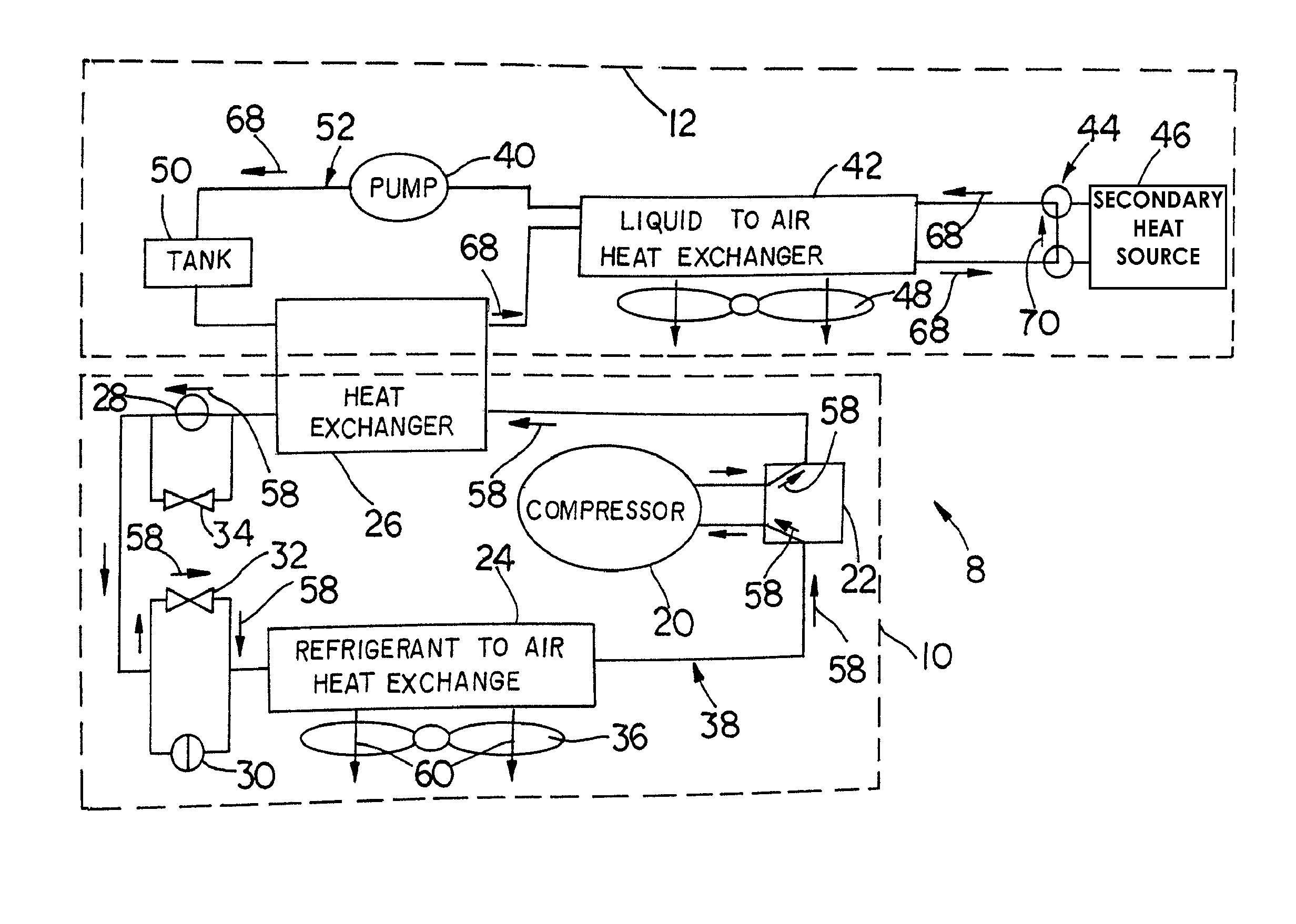
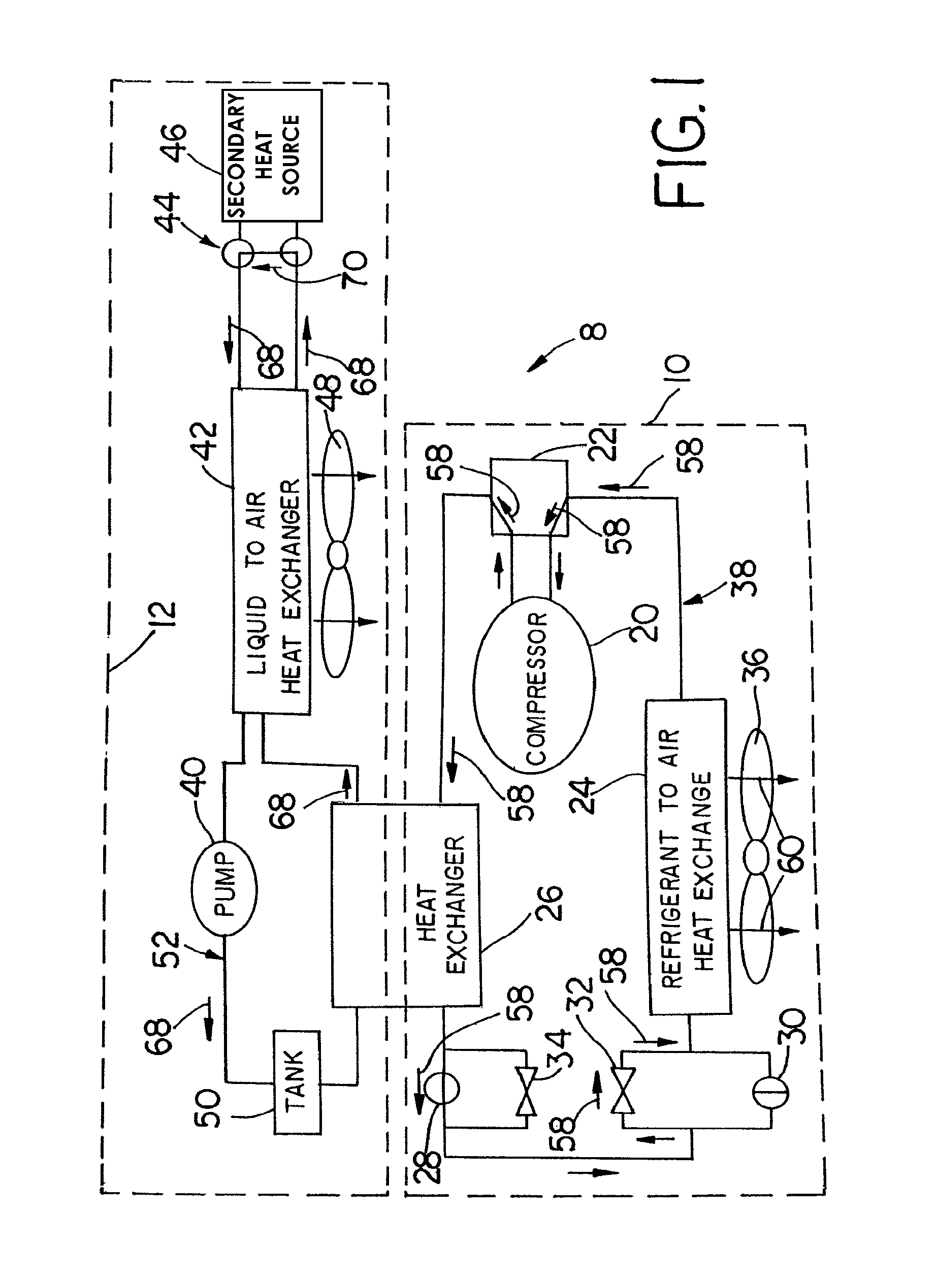
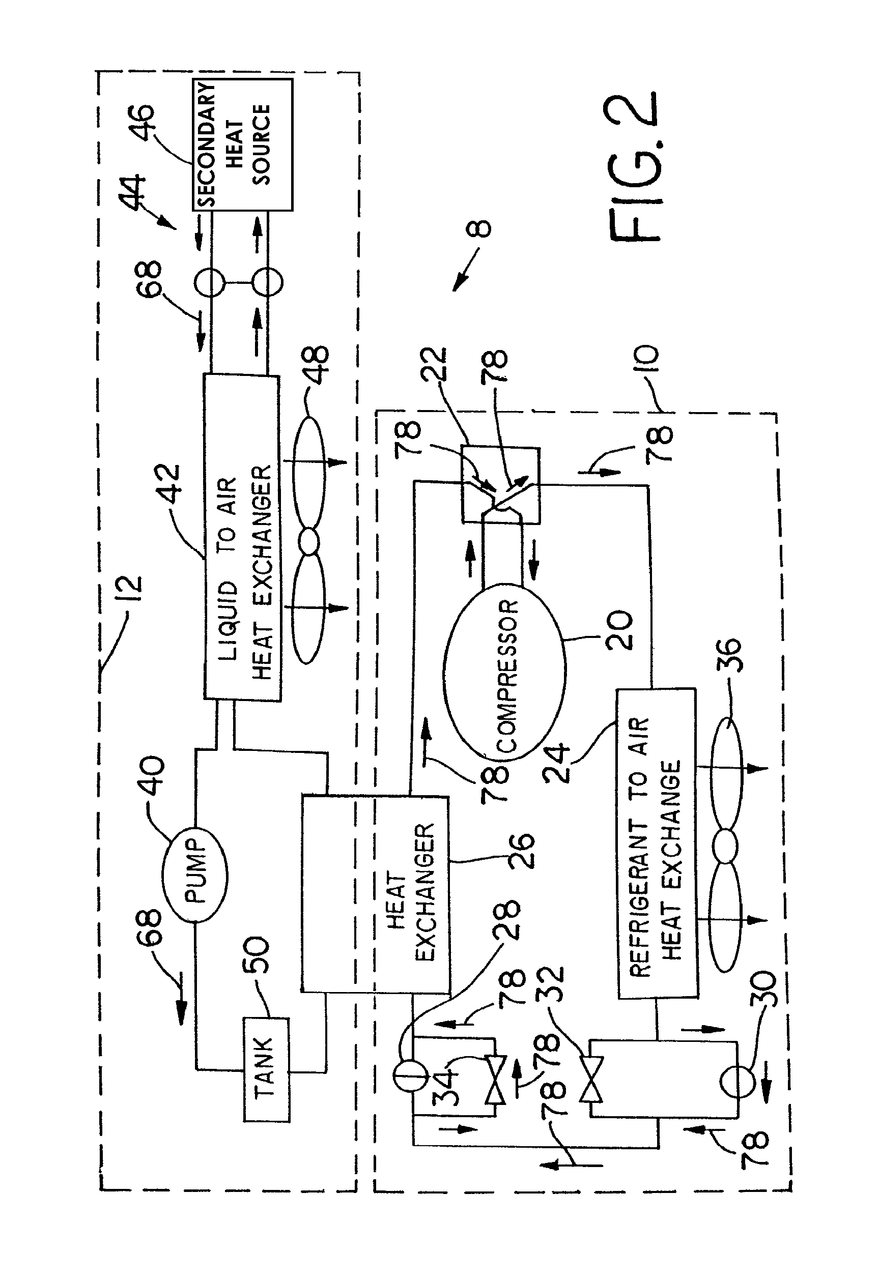
[0023]FIG. 1 illustrates a simplified block diagram of a preferred embodiment of a heating, ventilation and air conditioning system (HVAC system), indicated as a whole as 8, for heating, ventilating and cooling a passenger compartment of a vehicle, preferably a passenger compartment of a bus. For the heating and cooling functions, the HVAC system 8 utilizes a primary heating and air condition loop (hereinafter the primary loop), indicated as a whole as 10, that is assisted by a parallel secondary heating and cooling loop (hereinafter the secondary loop), indicated as a whole as 12. The primary loop 10 is a heating and air conditioning heat pump system utilizing a high pressure refrigerant process to either heat or cool the passenger compartment. A heat pump operates to transfer heat from one medium to another. The secondary loop 12 is a low pressure liquid system that selectively transfers heat from or to the primary loop 10.

[0024]The primary loop 10 is a high pressure refrigerant h...


PUM


Abstract

An HVAC system for heating and cooling a passenger compartment of a vehicle includes a first heat exchanger that transfers heat between a primary loop and a secondary loop. The primary loop is a reversible loop and uses high pressure refrigerant. A compressor pressurizes the refrigerant. A second heat exchanger selectively transfers heat energy to and from the passenger compartment. The secondary loop is a low pressure liquid coolant loop that passes through the first heat exchanger. A pump moves fluid through the secondary loop. A third heat exchanger transfers heat to and from an external medium from the fluid passing through the secondary loop. A secondary heat source adds heat to the secondary loop during a heating mode. A bypass means selectively bypasses the secondary heat source during a cooling mode.

Description

FIELD OF THE INVENTION[0001]This invention generally relates to air conditioning systems. More particularly, this invention relates to vehicle mounted air conditioning systems for over the road vehicles.BACKGROUND OF THE INVENTION[0002]In today's fast-paced, on-the-move society, buses are used to transport a large number of people from location to location. Bus manufacturers have continued to increase their emphasis on ergonomic factors in the design and manufacture of their vehicles. Indeed, the passenger compartment of a modem bus contains many features to improve the passenger's comfort. These features include, for example, audio and video systems, improved seats, including variable position seating, lumbar supports in the seats, increased sound insulation, and heating, ventilation, and air conditioning systems (HVAC systems) that provide a comfortable environment for a large quantity of passengers.[0003]To condition the air of the passenger compartment, many of the HVAC systems ...

Claims


Application Information

Patent Timeline
Patent Type & Authority Patents(United States)
IPC IPC(8): B60H1/00F25B13/00
CPCB60H1/00907F25B13/00B60H2001/00928F25B2313/004F25B2313/02741
Inventor ZEIGLER, TERRY A.BRACEY, JOHN S.CONNELL, BRETT SEANSLOAN, SCOTT
Owner BERGSTROM INC
Learn More