Gas turbine fuel injector mounting system

a technology of fuel injectors and mounting systems, which is applied in the field ofcombustor, can solve the problems of wear and/or cracks in each swirler, the inability to exchange each swirler and/or heat shield, and the damage of each heat shield, etc., and achieve the effect of ensuring the intrinsic life of the support member or cowling, and being easy to take ou

Active Publication Date: 2013-08-20
KAWASAKI HEAVY IND LTD
View PDF19 Cites 1 Cited by
  • Summary
  • Abstract
  • Description
  • Claims
  • Application Information

AI Technical Summary

Benefits of technology

[0014]According to the gas turbine combustor of this invention, the swirler unit provided by connecting the swirler and heat shield together is detachably attached to the support member via the fastening member. Therefore, only the swirler unit can be readily taken out by unfastening the fastening member, upon exchanging the swirler and / or heat shield. Further, there is no need for cutting the support member and / or cowling. Therefore, the intrinsic life span of the support member or cowling can be adequately ensured.

Problems solved by technology

In the above gas turbine combustor, wear and / or cracks sometimes occur in each swirler by fretting against the fuel injection valve.
Further, each heat shield is sometimes partly damaged by the combustion.
However, in the prior art gas turbine combustor as described above, it is not so easy to exchange each swirler and / or heat shield.
Thus the working efficiency is bad as well as the life span of the support member and / or cowling is short.

Method used


Image

  • Gas turbine fuel injector mounting system
  • Gas turbine fuel injector mounting system
  • Gas turbine fuel injector mounting system

Examples


Embodiment Construction

[0021]Hereinafter, preferred embodiments of the present invention will be described with reference to the drawings.

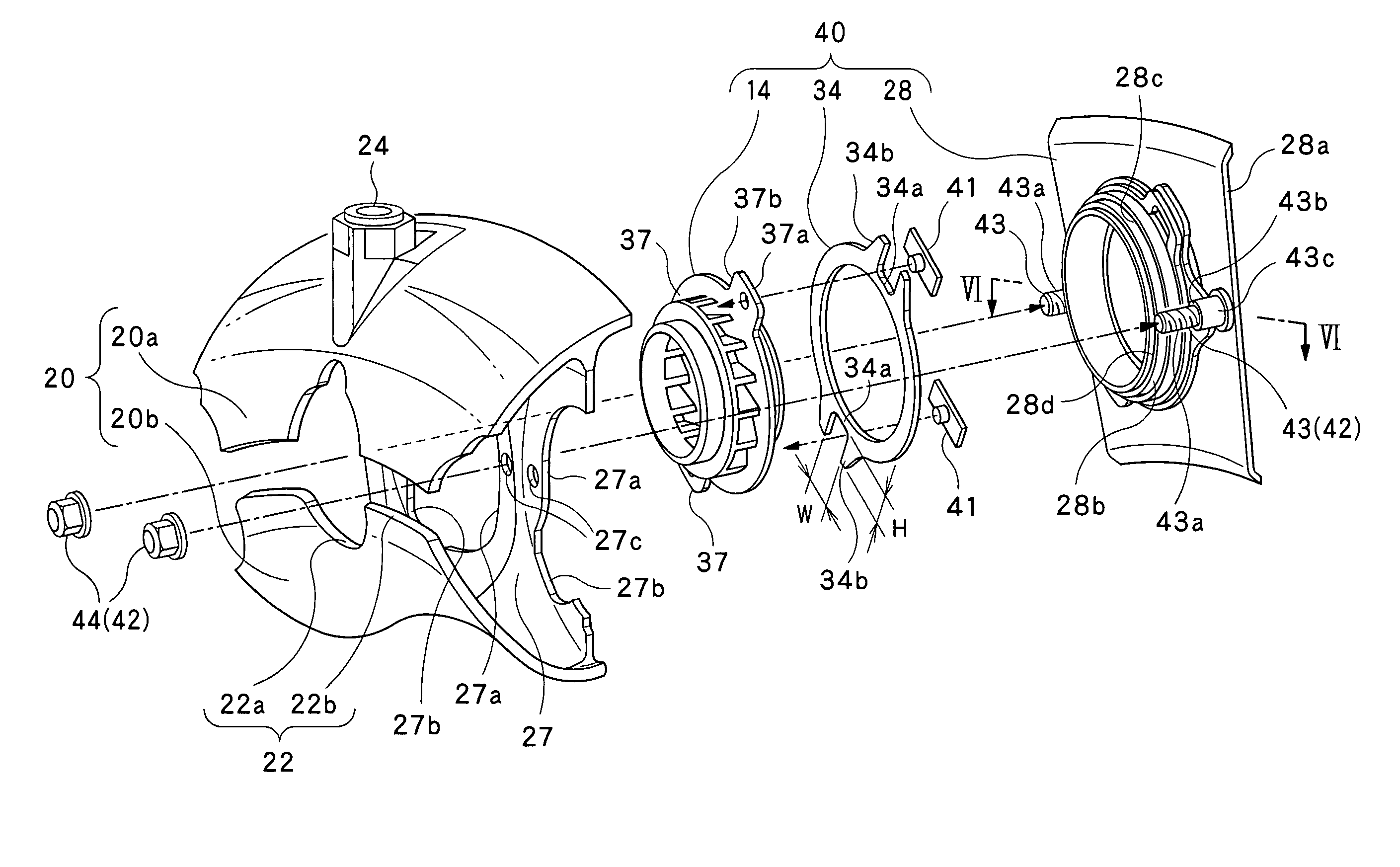
[0022]As shown in FIG. 1, a gas turbine engine is configured to drive a turbine, by combusting a mixed gas produced by mixing a fuel with the compressed air supplied from a compressor (not shown) of the gas turbine engine, and then by feeding the so-produced high-temperature and high-pressure combustion gas, generated by the combustion, to the turbine.

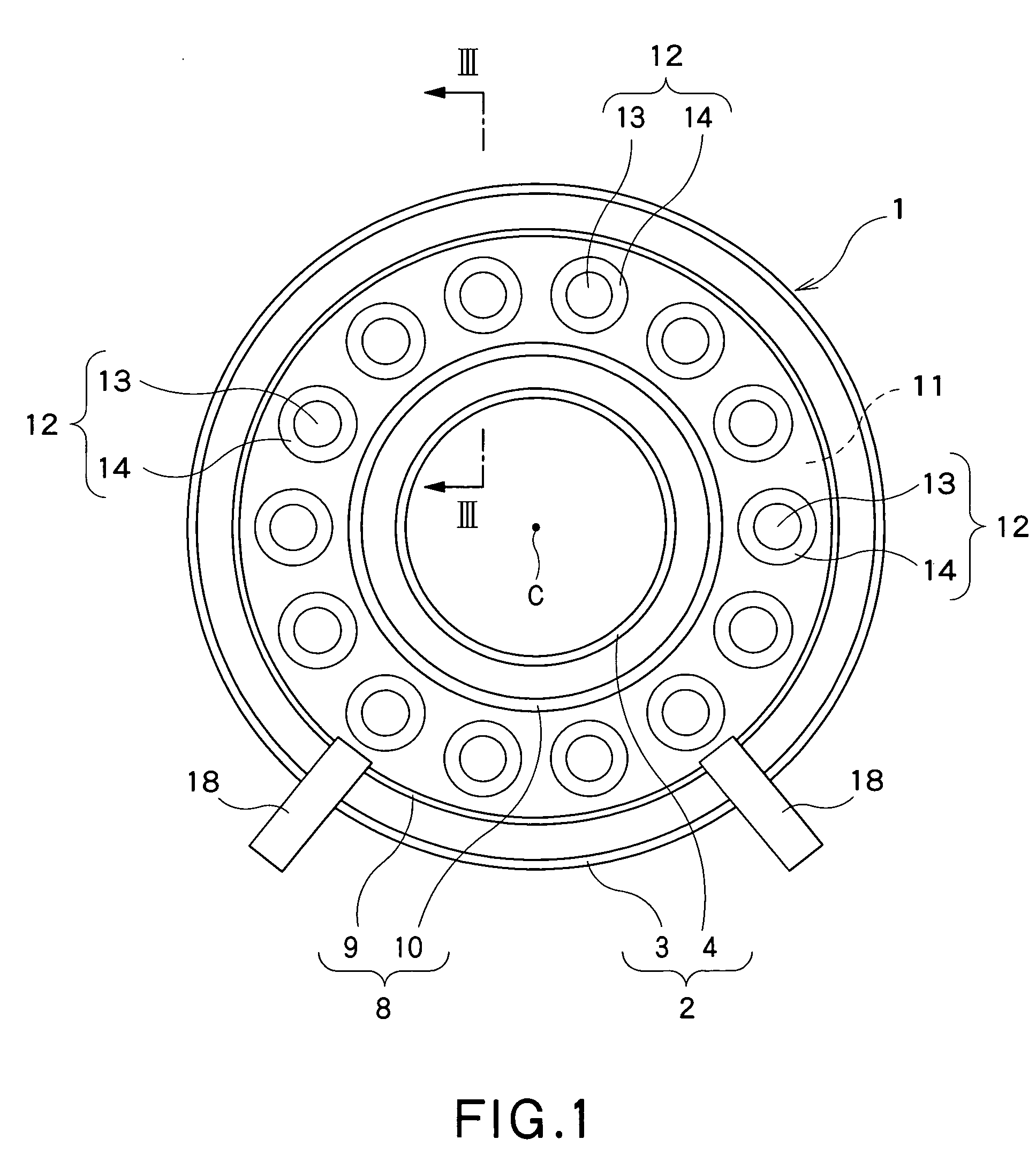
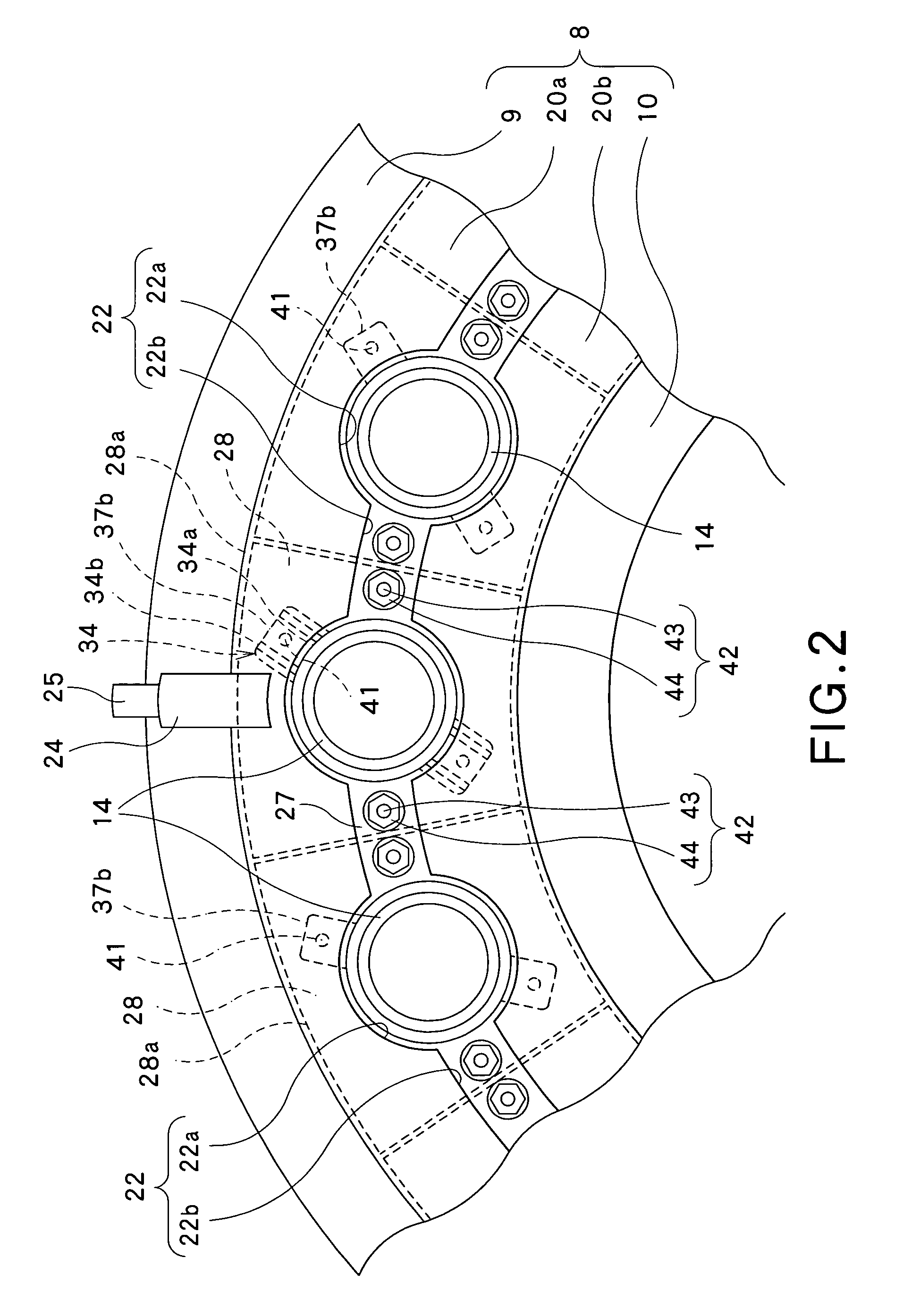
[0023]The gas turbine combustor 1 is of an annular type that is concentric with an axis C of the gas turbine engine. In this gas turbine combustor 1, an annular inner casing 4 is concentrically arranged inside an annular outer casing 3. In this case, the annular inner casing 4 and the annular outer casing 3 constitute a housing 2 which has an annular internal space formed therein. In the annular internal space of the housing 2, a combustion cylinder 8 is provided concentrically relative to the housing 2. This combustion cy...


PUM


Abstract

A gas turbine combustor, which can enable only a swirler and a heat shield to be readily taken out from the combustor upon the exchange the swirler and the heat shield. The gas turbine combustor includes: a combustion cylinder; a fuel injection unit for supplying fuel to a head portion of the combustion cylinder; a support member configured for allowing the fuel injection unit to be supported by the combustion cylinder; and a heat shield adapted for heat-insulating the support member from combustion gas in the combustion chamber, wherein the fuel injection unit includes a fuel injection valve for injecting the fuel, and a swirler for supplying compressed air to the fuel injected from the fuel injection valve while swirling the compressed air. The swirler and heat shield are connected together, constituting a swirler unit. This swirler unit is detachably attached to the support member via a fastening member.

Description

CROSS REFERENCE TO RELATED APPLICATIONS[0001]This application is based upon the prior Japanese Patent Application No. 2009-159452 filed on Jul. 6, 2009, the entire contents of which are incorporated herein by reference.TECHNICAL FIELD[0002]The present invention relates to a combustor for used in a gas turbine and / or airplane jet engine (the combustor is referred to as the “gas turbine combustor” hereinafter).BACKGROUND ART[0003]In the gas turbine combustor of this type, an annular type one is widely used. Further, as the annular type combustor, the combustor having a certain structure is known, wherein fuel injection valves for injecting the fuel are provided to a head portion of a combustion cylinder, and a swirler adapted for swirling compressed combustion air to stabilize the combustion is attached around an outer circumference of each fuel injection valve, and a support member configured for supporting each swirler in a cowling of the combustion cylinder is heat-insulated from c...

Claims


Application Information

Patent Timeline
Patent Type & Authority Patents(United States)
IPC IPC(8): F02C7/20
CPCF23R3/14F23R3/60
Inventor IMAMURA, TOHRUOGATA, HIDEKIHIDANI, KUNIO
Owner KAWASAKI HEAVY IND LTD
Why Eureka
Try Eureka