
Robot hand and control system, control method and control program for the same

a technology of hand and control system, applied in the field of hand, can solve the problems of difficult to control the bending and stretching operation of the finger mechanism with high accuracy, and affect the stability of the control of the finger mechanism movement, and achieve the effect of high-quality control of the bending and stretching movement of the finger mechanism

Active Publication Date: 2013-08-06
HONDA MOTOR CO LTD
View PDF38 Cites 18 Cited by
  • Summary
  • Abstract
  • Description
  • Claims
  • Application Information

AI Technical Summary

Benefits of technology

[0007]Accordingly, an object of the present invention is to provide a system and the like capable of stably controlling the movement of a finger mechanism with high accuracy, while enhancing the freedom degree of the layout of a pipe and the like at the same time.
[0010]The robot hand and the control system and the like for the same according to the first aspect of the present invention make it possible to provide a pipe with a degree of flexibility that is sufficient to allow a change in the cross-sectional area thereof according to the pressure of a fluid, thereby permitting a higher degree of freedom of the layout of the pipe and the master cylinder connected therethrough. Moreover, a change in the cross-sectional area of the pipe caused by a change in the fluid pressure in the pipe is taken into account, so that the position of the slave piston can be measured with high accuracy. Thus, the movements of the finger mechanisms can be stably controlled on the basis of a measured position of the slave piston.
[0012]According to the robot hand and the control system and the like for the same in accordance with the second aspect of the present invention, a difference between a measured outflow pressure of the fluid into the pipe from the master cylinder and a measured inflow pressure of the fluid into the slave cylinder from the pipe is determined. The difference indicates the degree of change in flow resistance of the fluid due to air getting into the fluid or an expansion or contraction of the pipe in the radial direction thereof and further indicates the degree of change in the responsiveness of a movement of the slave piston relative to a movement of the master piston. With this arrangement, the outflow amount of the fluid into the pipe from the master cylinder is adjusted on the basis of the difference, thus compensating for a change in the responsiveness of the movement of the slave piston relative to the movement of the master piston. This permits highly accurate control of the bending and stretching movements of the finger mechanisms.

Problems solved by technology

On the other hand, a change in the diameter of a flexible pipe caused by a change in the pressure of the medium in the pipe may impair the stability of the control of the finger mechanism movement.
Further, there are cases where air getting into the pipe or the like prevents a fluid pressure generated by the second cylinder from being adequately transmitted to the first cylinder.
This inconveniently makes it difficult to control the bending and stretching operation of the finger mechanism with high accuracy.

Method used


Image

  • Robot hand and control system, control method and control program for the same
  • Robot hand and control system, control method and control program for the same
  • Robot hand and control system, control method and control program for the same

Examples


Embodiment Construction

[0027]An embodiment of the present invention will be described with reference to the accompanying drawings.

[0028]First, the construction of a robot having robot hands as constituent elements representing an embodiment of the present invention will be described.

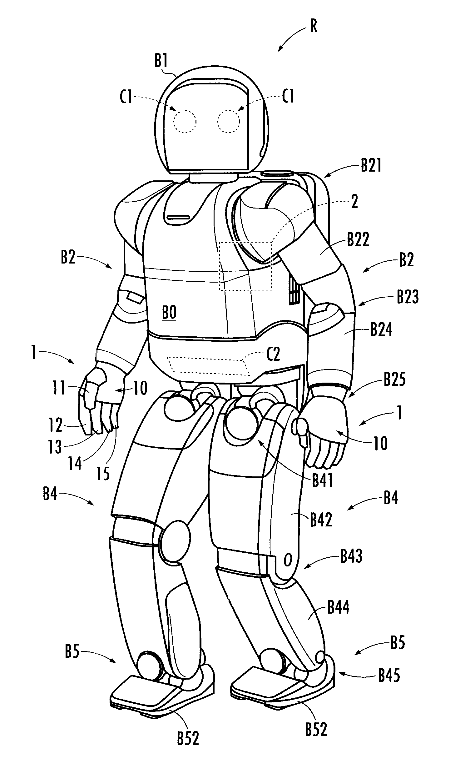
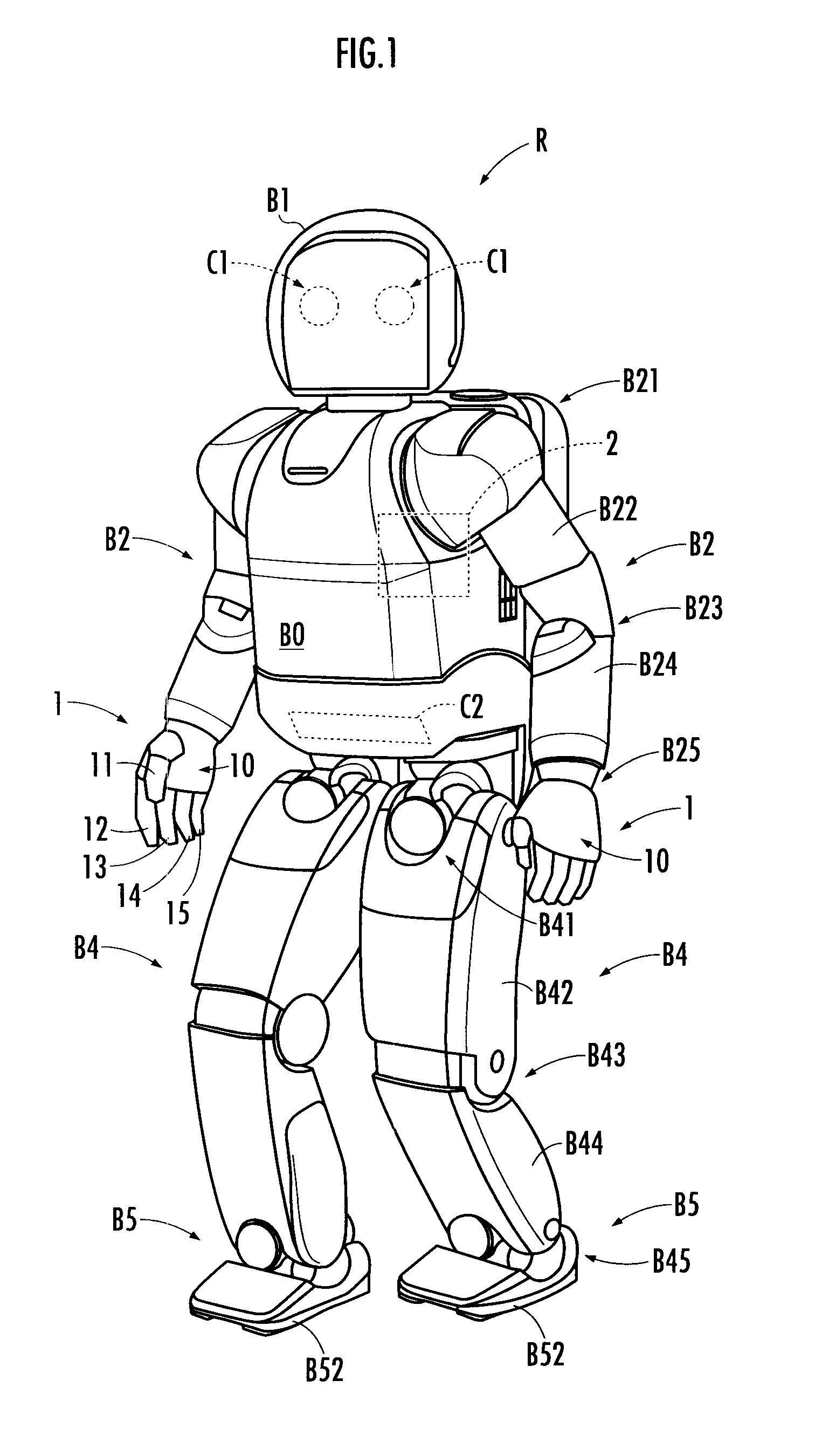
[0029]A robot R shown in FIG. 1 is a legged mobile robot. Like a human being, the robot R has a body B0, a head B1 disposed on the top of the body B0, right and left arms B2 extended from both sides of an upper portion of the body B0, hands 1 provided at the distal ends of the right and left arms B2, and right and left legs B4 extended downward from the bottom of the body B0. The robot R is not limited to the legged mobile robot but may also be any type of robot provided with mechanisms corresponding to the arms B2 for changing the positions and postures of the hands 1.

[0030]The robot R is provided with a controller 2 which controls the movements of the robot R. The controller 2 may be a decentralized controller constructed of...


PUM


Abstract

A robot hand has a pipe which is sufficiently flexible to allow a change in the cross-sectional area thereof according to the pressure of a fluid, thereby permitting a higher degree of freedom of the layouts of the pipe and a master cylinder connected through the pipe. Moreover, considerations are given to a change in the cross-sectional area of the pipe caused by a change in the pressure of the fluid in the pipe, thus making it possible to measure the position of a slave piston with high accuracy.

Description

BACKGROUND OF THE INVENTION[0001]1. Field of the Invention[0002]The present invention relates to a robot hand which is provided with a palm and a plurality of fingers extended from the palm and which carries out an operation of holding an object by adjusting the position and the posture of the palm and by moving each of the plurality of fingers.[0003]2. Description of the Related Art[0004]A technique for controlling the movement of a finger mechanism, which is a constituent element of a robot hand, by using a medium of a gas or a liquid, such as oil, has been proposed (refer to Japanese Patent Application Laid-Open No. 2003-039370). The finer mechanism is mechanically connected to a first piston of a first cylinder, and the first cylinder is connected to a second cylinder through a pipe. The first piston is driven forward and backward as a second piston of the second cylinder is driven forward and backward, thereby driving the finger mechanism. The movement of the second piston is c...

Claims


Application Information

Patent Timeline
Patent Type & Authority Patents(United States)
IPC IPC(8): G06F19/00G05B15/00
CPCB25J9/1612B25J15/0009G06N3/008
Inventor TAKAHASHI, KAZUYUKIWAITA, HIRONORIGOMI, HIROSHI
Owner HONDA MOTOR CO LTD
Learn More