
Configurable rotary spray nozzle

a rotary spray nozzle and configuration technology, applied in the direction of spray nozzles, movable spraying apparatus, spraying apparatus, etc., can solve the problem that the rotary spray nozzle must be completely replaced, and achieve the effect of reducing manufacturing and maintenance costs and cos

Active Publication Date: 2013-08-06
SONNYS HFI HOLDINGS LLC
View PDF32 Cites 7 Cited by
  • Summary
  • Abstract
  • Description
  • Claims
  • Application Information

AI Technical Summary

Benefits of technology

This design reduces manufacturing and maintenance costs, provides environmental protection, and allows for customizable spray performance by using a separable external shell to replace or modify internal components, extending the nozzle's lifespan and adaptability.

Problems solved by technology

As use of the rotary spray nozzles is often conducted in harsh and unforgiving environments, the individual components can experience failure such that the rotary spray nozzle must be completely replaced.

Method used


Image

  • Configurable rotary spray nozzle
  • Configurable rotary spray nozzle
  • Configurable rotary spray nozzle

Examples


Embodiment Construction

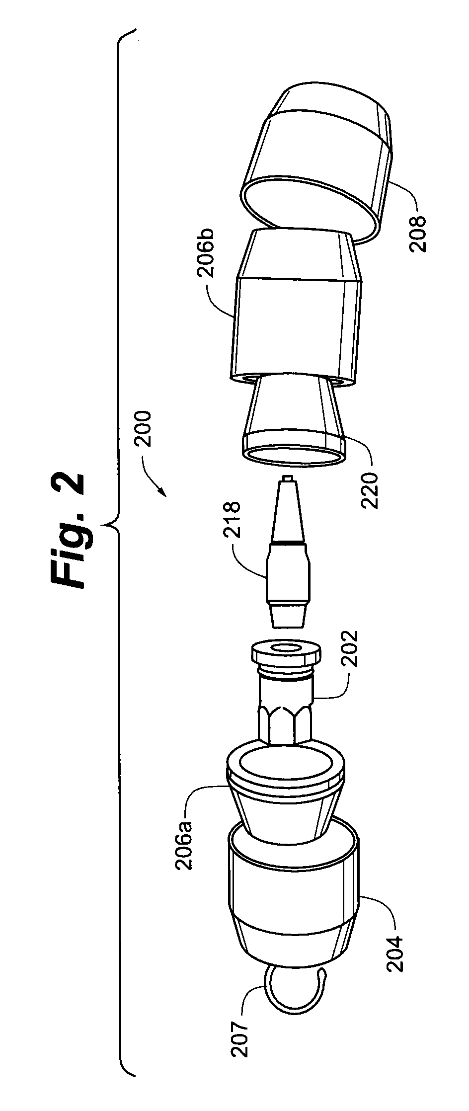
[0022]Referring now to FIG. 1, a conventional rotary spray nozzle 100 of the prior art generally comprises an inlet member 102, an endcap 104, a housing member 106 and a cover 108. Typically, at least inlet member 102, endcap 104 and housing member 106 are machined from metal or metal alloy blocks such as, for example, aluminum, brass, stainless steel and the like. A rotor 110, one or more o-rings 112 and a seat 114 generally reside within conventional rotary spray nozzle 100. In operation, a fluid to be sprayed enters the inlet member 102 where it is routed by fluid passages within the endcap 104. The fluid passages with the endcap 104 direct the water in a tangential direction to the incoming flow such that the fluid is directed against the housing member 106. The fluid causes rotor 110 to spin inside the housing member 106. As the rotor 110 is spinning, the fluid enters a rotor inlet 116, flows through a rotor lumen 118 and exits a rotor outlet 120. At the rotor outlet 120, rotor...


PUM


Abstract

A configurable rotary spray nozzle having lower manufacturing and maintenance costs through the use of an external shell providing strength and resistance to damage such that molded internal components can be utilized to provide the desired spray characteristics. The molded internal wet components can comprise molded polymeric structures that allow for the formation of complex flow geometries and structures that are either impossible or economically impractical to achieve with conventional tooling and machining operations. The use of an external shell provides for use of replacement kits to maintain or otherwise replace worn and / or damaged internal wet components while reusing the external housing. The use of the external shell also allows a user to customize and change spray performance of the configurable rotary spray nozzle by swapping internal wet components having selected flow geometries and characteristics so as to provide a desired spray performance.

Description

PRIORITY CLAIM[0001]The present application claims priority to U.S. Provisional Application Ser. No. 61 / 023,314, filed Jan. 24, 2008, and entitled “CONFIGURABLE ROTARY SPRAY NOZZLE”, which is herein incorporated by reference in its entirety.FIELD OF THE DISCLOSURE[0002]The present disclosure is directed to a rotary spray nozzle for use in both high and low pressure spray applications. More specifically, the present invention is directed to a rotary spray nozzle having internal nozzle components molded from suitable polymers and a metal housing enclosing the internal nozzle components.BACKGROUND OF THE DISCLOSURE[0003]Rotary spray nozzles are well known and are frequently used in spray applications such as, for example, automated car wash applications. Conventional rotary spray nozzles are essentially metallic structures having an internal rotor with one or more elastomeric o-rings for increasing friction and controlling rotation speed. Representative metallic materials for construct...

Claims


Application Information

Patent Timeline
Patent Type & Authority Patents(United States)
IPC IPC(8): B05B3/04
CPCB05B3/0463
Inventor BROWN, GARYHARRIS, JAIMEKENNSINGER, DAVEMOLITOR, CHRIS
Owner SONNYS HFI HOLDINGS LLC
Learn More