Selector lever having actuating change of position

a technology of shifter lever and shifter, which is applied in the direction of mechanical control device, process and machine control, instruments, etc., can solve the problems of motor vehicle transmission in engine compartment no longer mechanically coupled, selector lever position no longer coinciding with transmission gear state, and actuating lever, etc., to achieve low design complexity, reliable visual and tactile feedback, and minimal construction space

Inactive Publication Date: 2013-08-06
ZF FRIEDRICHSHAFEN AG
View PDF18 Cites 10 Cited by
  • Summary
  • Abstract
  • Description
  • Claims
  • Application Information

AI Technical Summary

Benefits of technology

[0011]Proceeding from this background, the problem addressed by the present invention is to create an operating device for a gear shifting transmission, with which the stated disadvantages found in the prior art can be overcome. The purpose of the invention is to reliably ensure that the selector lever position always reflects the actual gear state of the transmission, even with shift-by-wire-controlled gear shifting transmissions, for example in the case of the P-position, whereby reliable visual and tactile feedback about the actual gear state of the transmission can be realized. The invention is to prevent particularly that the selector lever, in the case of an automatically engaged park lock (“Auto-P”), remains misleadingly in the last engaged shift position. In contrast to the solutions known from the prior art, this functionality is to be implemented, however, with low design complexity, minimal construction space and without generating disruptive noises.

Problems solved by technology

However, when gear shifting transmissions are actuated electrically or using shift-by-wire, the actuating lever in the passenger compartment and the motor vehicle transmission in the engine compartment are no longer mechanically coupled in this manner.
In by-wire actuated gear shifting transmissions, however, the absence of a mechanical connection between the transmission actuator system and the selector lever can, under certain basic conditions or in the case of an error, also lead to the selector lever position no longer coinciding with the gear state of the transmission.
This discrepancy between the selector lever position and transmission state could therefore lead to undesired operating errors or incorrect conclusions by the driver.
This known operating device is, however, associated with a certain design complexity in order to implement the desired actuating mobility of the selector lever, with the corresponding consequence of construction space and costs.
It must also be expected that the electromotive drive and the reduction gear that are present there can generate disruptive noises.
The motor or hydraulic drive of the ramp in this known device is, however, also relatively complex and requires considerable construction space.
In the case of a drive using an electric gear motor noise problems are also to be expected.

Method used


Image

  • Selector lever having actuating change of position
  • Selector lever having actuating change of position
  • Selector lever having actuating change of position

Examples


Embodiment Construction

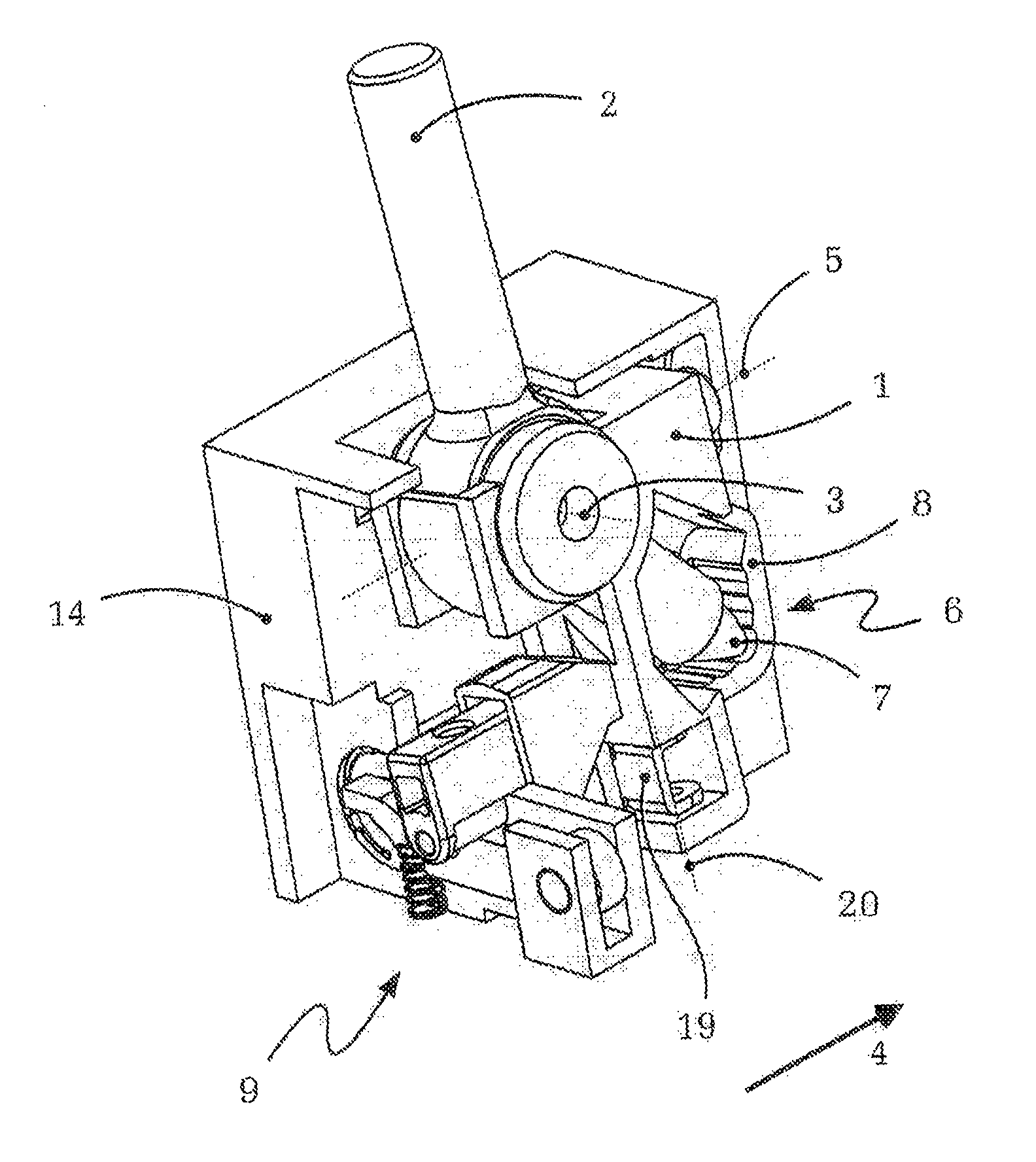
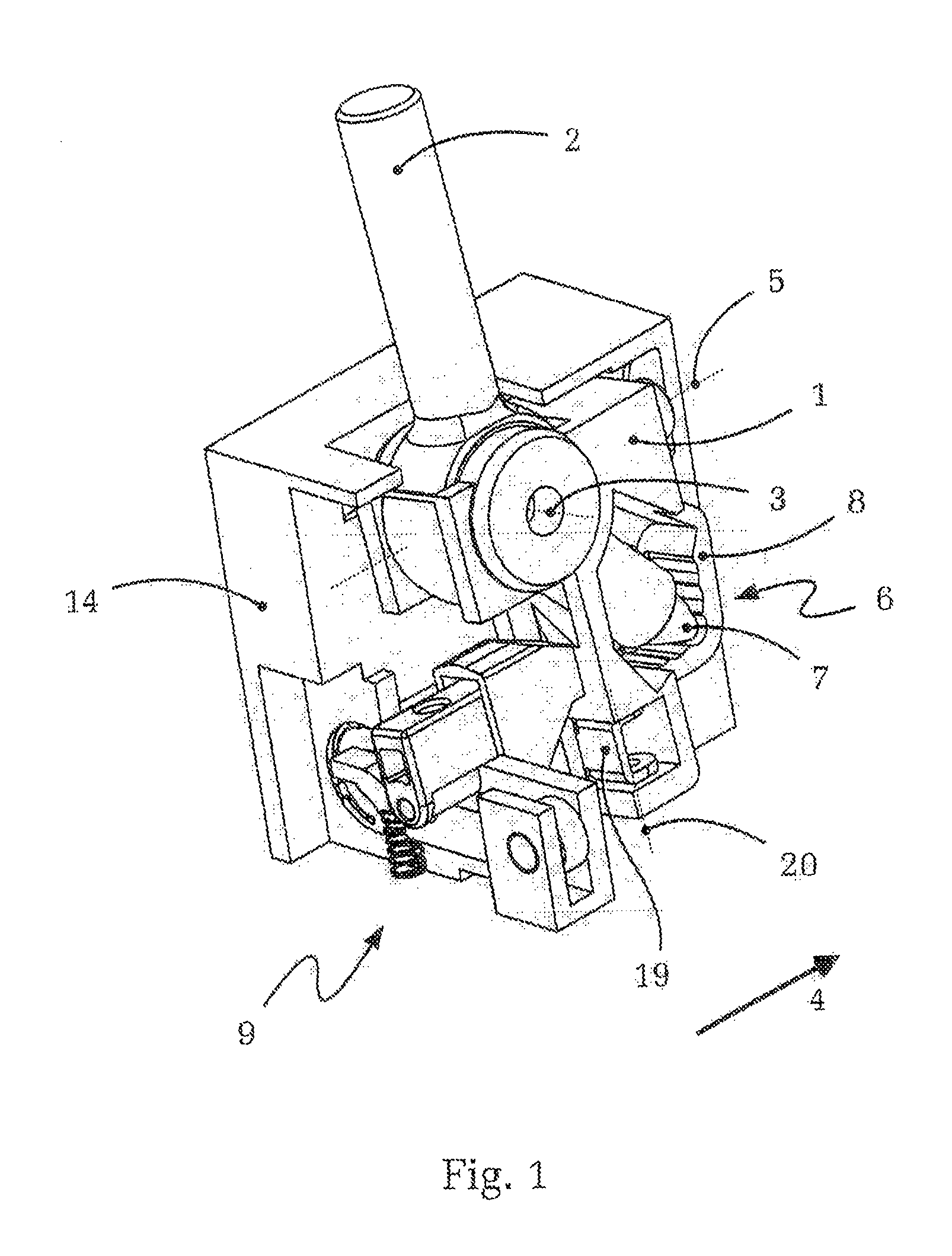
[0036]FIG. 1 shows, in a schematic, isometric depiction one embodiment of an operating device according to the present invention. For better understanding and improved clarity, parts of the housing base 14, the crosspiece 1 and the selector lever 2 are not shown in FIG. 1.

[0037]Here, the actuation lever or selector lever 2 can be seen mounted in a crosspiece 1. The selector lever 2, due to its mounting in the crosspiece 1, can be moved about a first pivot axis 3 back and forth relative to the direction of travel 4 of the motor vehicle, while the crosspiece 1 together with the selector lever 2 can pivot laterally back and forth about a second pivot axis 5. In this manner, the two degrees of freedom of movement of the selector lever 2 are defined—for example, within a typical shift pattern of a manual gear actuation, or in the shift pattern of an automatic transmission having an additional manual shift gate.

[0038]The operating device according to FIG. 1 has two detent mechanisms. The ...


PUM


Abstract

An operating device for shift-by-wire transmission comprises a selector lever which has a detent mechanism. The detent mechanism comprises bevel and notched contours that can be displaced for automatically returning the selector lever back to the first lock position or shift gate. The notched contour is spring-biased toward the selector lever detent element and overlaps the bevel contour in its first position, and an actuating block is provided for locking the notched contour in its first position near the detent element. The spring-loading of the notched contour is weaker than the spring-loading of the detent element, and the shape of the first detent position of the notched contour matches that of the first detent position of the bevel contour when the notched contour is located in the first position. The operating device enables actuator-controlled automatic return, and optional locking of the selector lever with little design effort, while simultaneously having low space requirements and minimal generation of any disturbing noise.

Description

[0001]This application is a National Stage completion of PCT / DE2009 / 050042, filed Aug. 11, 2009, which claims priority from German patent application serial no. 10 2008 041 374.7, filed Aug. 20, 2008.FIELD OF THE INVENTION[0002]The invention relates to an operating device for a gear shifting transmission, e.g. for a manual or automatic transmission having shift-by-wire actuation.BACKGROUND OF THE INVENTION[0003]Gear shifting transmissions of motor vehicles are generally shifted or controlled by means of an operating device disposed within reach of the driver. Actuating elements such as shift levers or selector levers are used regularly for this purpose, and are located, for example between the front seats of the motor vehicle or in other regions of the cockpit.[0004]In the case of mechanical transmission control or mechanical coupling between the selector lever and the gear shifting transmission—using a cable or linkage for example, the selector lever position always coincides with ...

Claims


Application Information

Patent Timeline
Patent Type & Authority Patents(United States)
IPC IPC(8): B60K20/00G05G5/08F16H59/04
CPCF16H61/22F16H61/24F16H2059/0295Y10T74/2011Y10T74/2014Y10T74/20116F16H2061/245F16H61/00
Inventor RAKE, LUDGERGIEFER, ANDREASROSENTRETER, SASCHA
Owner ZF FRIEDRICHSHAFEN AG
Why Eureka
Try Eureka