Mount damper and image forming apparatus using the mount damper
a technology of damper and image forming apparatus, which is applied in the direction of shock absorbers, instruments, applications, etc., can solve problems such as deteriorating image quality, and achieve the effect of preventing resonance and absorbing vibration reliably and constantly
- Summary
- Abstract
- Description
- Claims
- Application Information
AI Technical Summary
Benefits of technology
Problems solved by technology
Method used
Image
Examples
first embodiment
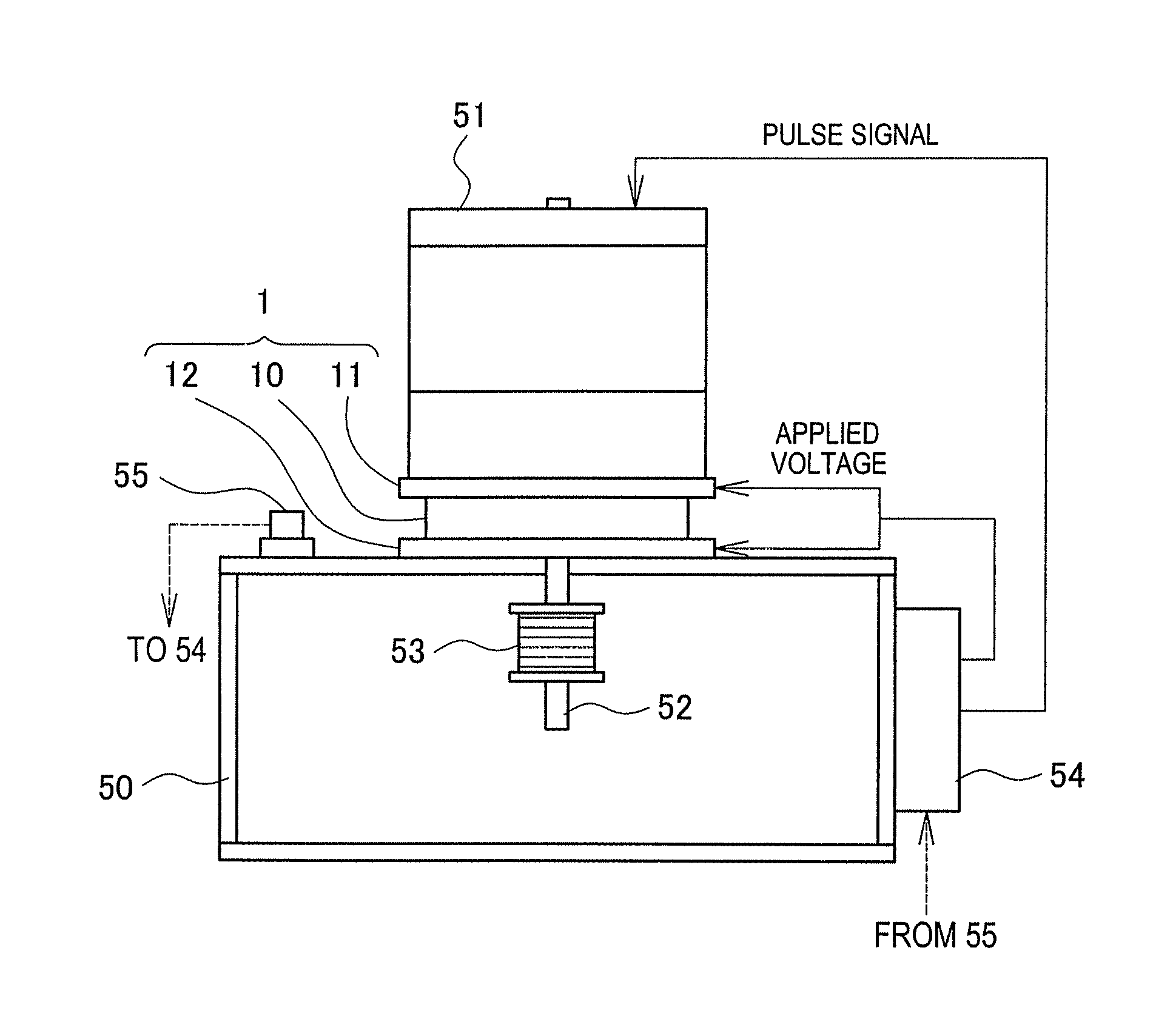
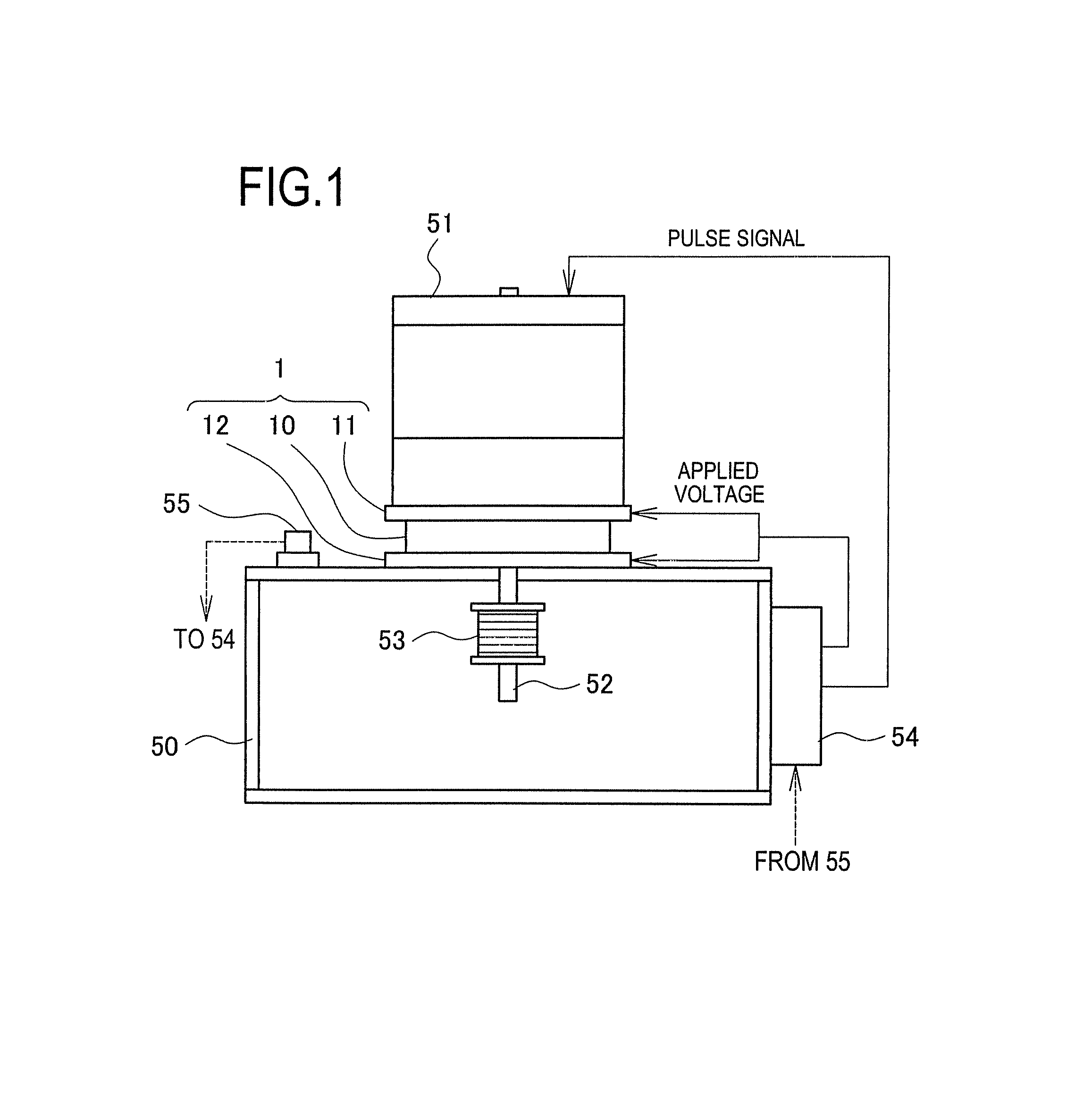
[0036]A mount damper of this embodiment is configured as shown in FIG. 1. FIG. 1 shows the mount damper 1 of this embodiment together with a support body 50 and a motor 51. Specifically, the motor 51 is mounted on the support body 51 through the mount damper 1 of this embodiment. The motor 51 is a stepping motor. The support body 50 shown in FIG. 1 is illustrated in a very simplified form as compared with an actual shape. A gear 53 is attached on a rotary shaft 52 of the motor 51. The rotary shaft 52 extends through the mount damper 1, and the gear 53 is located inside the support body 50. The support body 50 is further provided with a control section 54 and a vibration sensor 55.
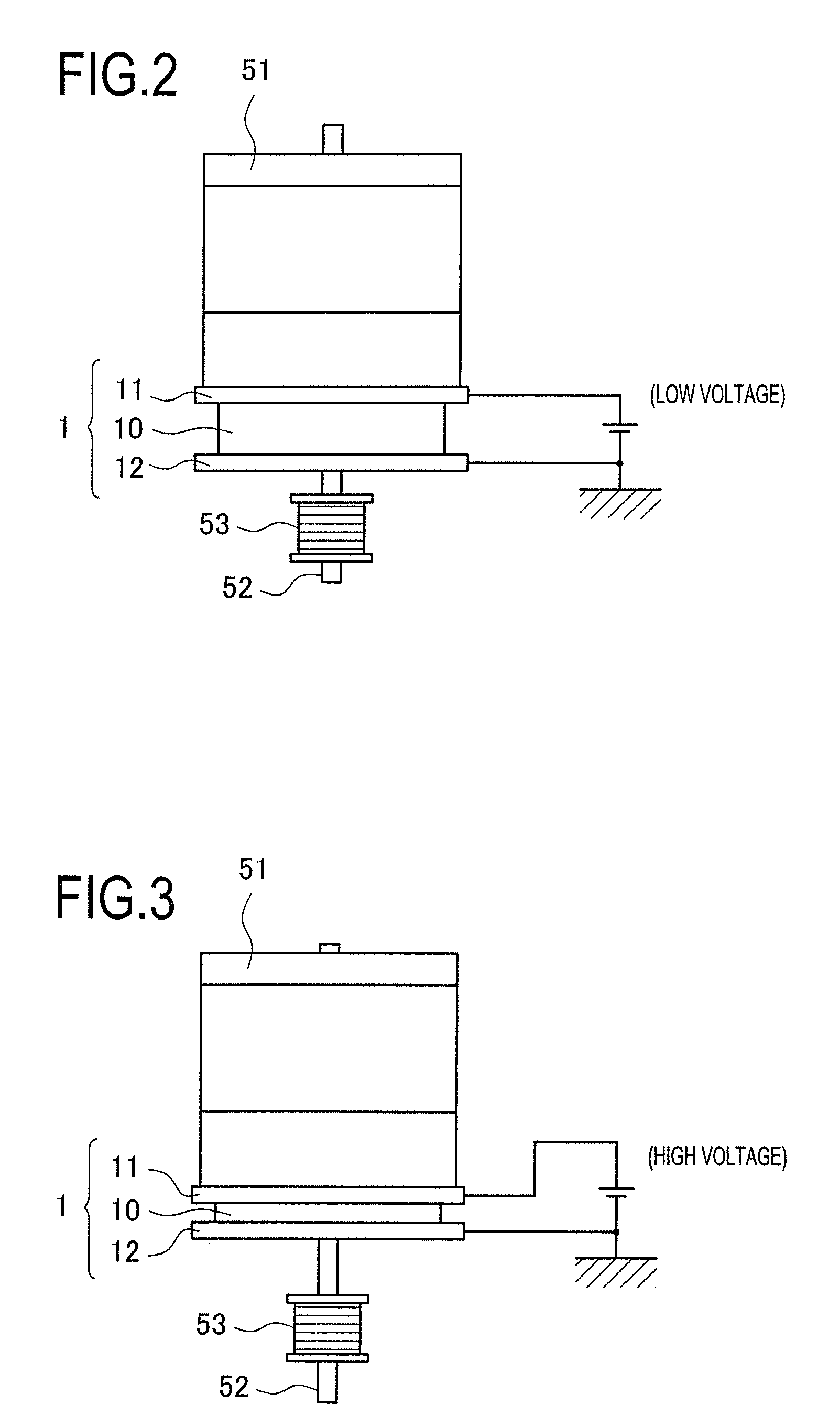
[0037]The mount damper 1 in FIG. 1 is configured such that an electrostrictive polymer member 10 is sandwiched between two electrode plates 11 and 12. These electrode plates 11 and 12 are bonded to both end faces of the electrostrictive polymer member 10. The electrode plate 11 is an electrode located on th...
second embodiment
[0065]A mount damper of this embodiment is constituted as shown in FIG. 13. In FIG. 13, the mount damper 2 of this embodiment is illustrated together with the motor 51 and the gear 53. In FIG. 13, the support body 50 and the control section 54 shown in FIG. 1 are omitted but they have the same configurations as those in the first embodiment.
[0066]The mount damper 2 in FIG. 13 is configured such that a rubber member 20 is sandwiched between two electrode plates 11 and 12 and polymeric artificial muscles 21 are attached around the electrode plates 11 and 12. This rubber member 20 has a property of increasing hardness when compressed and decrease hardness when extended. However, it is a mere extendible and contractible member, which does not serve as an actuator capable of expanding and contracting by itself such as the electrostrictive polymer member 10 of the first embodiment.
[0067]In this embodiment, it is the polymeric artificial muscles 21 to serve the above function as an actuato...
embodiment adopted
in Image Forming Apparatus
[0070]An example of applying the mount damper of the present invention to a rotary drive system of an image forming apparatus now will be explained. The mount damper used in the image forming apparatus may be either one of the mount damper in the first embodiment or that in the second embodiment. An image forming apparatus 100 shown in FIG. 16 includes, from top, a document feeder 101, an image scanner 102, a main unit 103, and a sheet feeder 104. The image scanner 102 is provided with a control panel 105.
[0071]The main unit 103 is configured to form an image on a sheet with toner and contains a well known photoreceptor, exposure unit, transfer unit, fixing unit, and other process units. This main unit 103 is further provided with a sheet reversing unit 106 for double-sided printing. The sheet feeder 104 includes two sheet feed cassettes 107 and 108. The image forming apparatus 100 is thus arranged such that the document feeder 101 feeds a document, the ima...
PUM
 Abstract
Description
Claims
Application Information
 - R&D
- Intellectual Property
- Life Sciences
- Materials
- Tech Scout
- Unparalleled Data Quality
- Higher Quality Content
- 60% Fewer Hallucinations
Browse by: Latest US Patents, China's latest patents, Technical Efficacy Thesaurus, Application Domain, Technology Topic, Popular Technical Reports.
© 2025 PatSnap. All rights reserved.Legal|Privacy policy|Modern Slavery Act Transparency Statement|Sitemap|About US| Contact US: help@patsnap.com


