
Laser device

a laser source and laser technology, applied in the field of lasers, can solve the problems of reducing limiting the potential output power, and not being compact or robust, and achieve the effect of narrowing the spectral width of the pulse and breaking the pulse spectral width

Inactive Publication Date: 2013-07-23
AUCKLAND UNISERVICES LTD
View PDF2 Cites 5 Cited by
  • Summary
  • Abstract
  • Description
  • Claims
  • Application Information

AI Technical Summary

Benefits of technology

[0034]Preferably the temporal pulse selection device shortens the temporal width of a pulse by virtue of selecting a portion of the spectral width of the pulse.
[0069]Preferably the temporal pulse selection device shortens the temporal width of a pulse by virtue of selecting a portion of the spectral width of the pulse.
[0103]Preferably the temporal pulse selection device shortens the temporal width of a pulse by virtue of selecting a portion of the spectral width of the pulse.
[0129]Preferably optical effect in the gain medium is broadening the spectral width of the pulse and the optical effect in the fibre optical system is narrowing the spectral width of the pulse.
[0134]Preferably the temporal pulse selection device shortens the temporal width of a pulse by virtue of selecting a portion of the spectral width of the pulse.

Problems solved by technology

A particular limitation of pulsed fibre based lasers is the nonlinear phase limit leading to a wave breaking effect leading to degradation of the pulse shape.
Each factor limits the potential output power.
Despite good performance of such cavities, they are not compact or robust.
Further, such lasers also suffer from having to couple light in and out of a fibre, leading to stability and inefficiency problems.

Method used


Image

  • Laser device
  • Laser device
  • Laser device

Examples


Embodiment Construction

[0158]Laser cavities for generating parabolic pulses or sustaining self similar propagation are difficult to implement as periodic repetition of the pulse shape is difficult to control, thereby making it difficult to implement periodic boundary conditions required to ensure the laser will operate. Such boundary conditions include maintaining substantially the same pulse characteristics at a consistent location during each round trip of the laser cavity. Such characteristics include the pulse temporal shape and the pulse spectral shape Due to these problems, the prior art has not provided a solution for implementing a mode-locked laser that avoids the use of free space components with all-normal dispersion for generating parabolic pulses or implementing self-similar propagation.

[0159]It is of great interest to develop a laser that generates parabolic pulses using a fibre gain medium. Raman gain media has been used to construct a parabolic pulse amplifier, however, the prior art has n...


PUM


Abstract

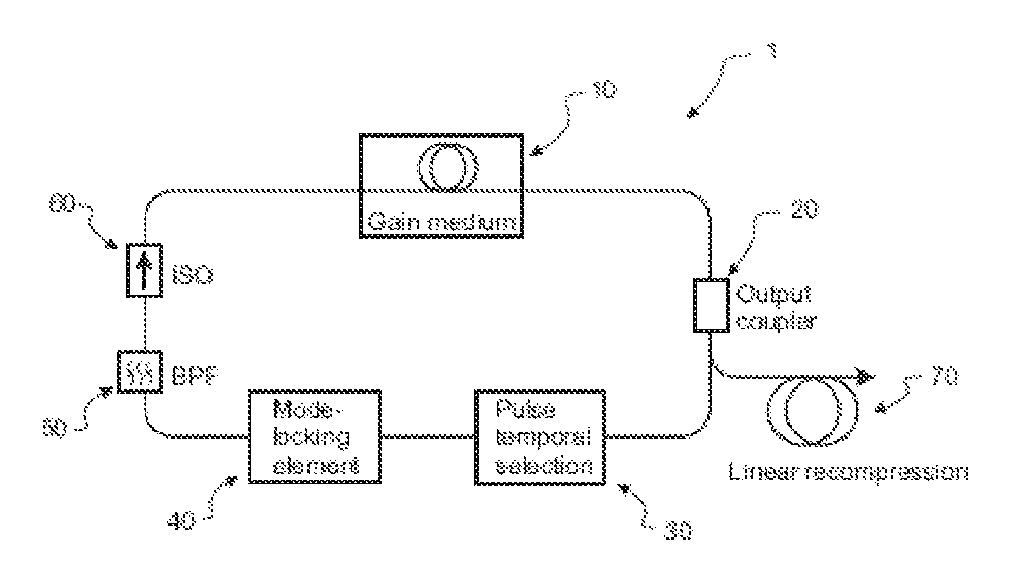
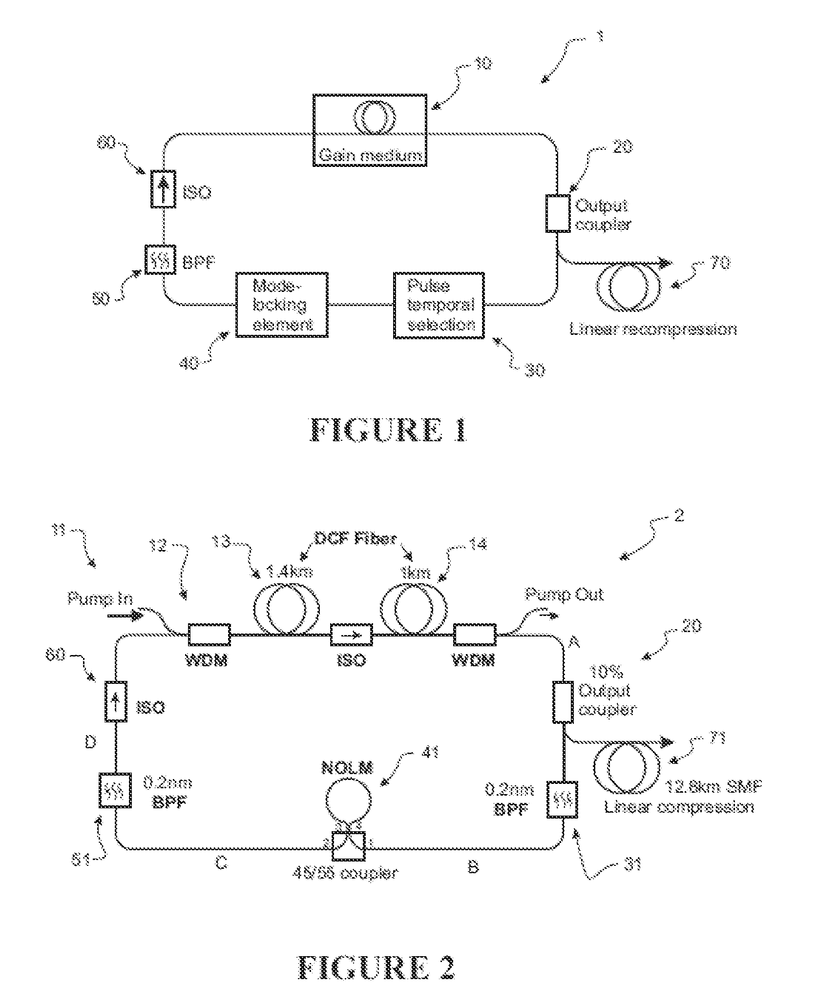
A laser apparatus for producing mode locked pulses includes a closed optical system adapted to connect to a fiber grain medium to form a laser cavity. The fiber gain medium is adapted to receive pulses characterized by a first state and to output pulses characterized by a second state. The closed optical system is adapted to receive the pulses in the second state and output pulses in a state similar to the first state.

Description

REFERENCE TO PRIOR APPLICATION[0001]This application claims the benefit of U.S. Provisional Application No. 61 / 473,248, filed Apr. 8, 2011 the entirety of which is incorporated herein by reference.FIELD OF THE INVENTION[0002]The present invention relates to lasers, and more particularly to pulsed laser sources.BACKGROUND TO THE INVENTION[0003]Fibre oscillators such as erbium or ytterbium doped fibre lasers as well as Raman amplifiers are reliable devices which are used in many different technology fields such as telecommunications, optical imaging, healthcare and metrology. Much effort has been dedicated to increasing the peak power of the pulses delivered by fibre based lasers as their stability and compact size make them an attractive alternative to bulky solid-state lasers. A particular limitation of pulsed fibre based lasers is the nonlinear phase limit leading to a wave breaking effect leading to degradation of the pulse shape. Fibre lasers also require dispersion management to...

Claims


Application Information

Patent Timeline
Patent Type & Authority Patents(United States)
IPC IPC(8): H01S3/30
CPCH01S3/06791H01S3/1112H01S3/302H01S3/06725H01S3/08027H01S3/0057H01S2301/08
Inventor AGUERGARAY, CLAUDEKRUGLOV, VLADIMIRBRODERICK, NEILHARVEY, JOHNMECHIN, DAVID
Owner AUCKLAND UNISERVICES LTD
Learn More