Method for detecting an environment of a vehicle

a technology for detecting an environment and a vehicle, applied in the direction of vehicle position/course/altitude control, process and machine control, instruments, etc., can solve the problems of high sensitivity of ultrasonic sensors at close range but only a limited range, relatively expensive sensors, and approaching vehicles posing a potential danger

Inactive Publication Date: 2013-07-23
ROBERT BOSCH GMBH
View PDF31 Cites 15 Cited by
  • Summary
  • Abstract
  • Description
  • Claims
  • Application Information

AI Technical Summary

Benefits of technology

[0010]As a result, it is possible to detect vehicles early enough to trigger warnings in timely fashion. The driver is able to be informed about the dangerous situation in an unambiguous manner. It should not be overlooked that, prior to entering the blind spot range, the approaching vehicle constitutes a potential danger nevertheless. By predicting the entrance time, it is possible to output warnings earlier.

Problems solved by technology

Ultrasonic sensors (USS) have high sensitivity at close range but only a limited range.
One possibility consists of using what is known as short range radar (SRR), which has a reach of up to 40 m. However, these sensors are relatively expensive and as yet have not received approval for the transmit frequency in Europe.
It should not be overlooked that, prior to entering the blind spot range, the approaching vehicle constitutes a potential danger nevertheless.

Method used


Image

  • Method for detecting an environment of a vehicle
  • Method for detecting an environment of a vehicle
  • Method for detecting an environment of a vehicle

Examples


Embodiment Construction

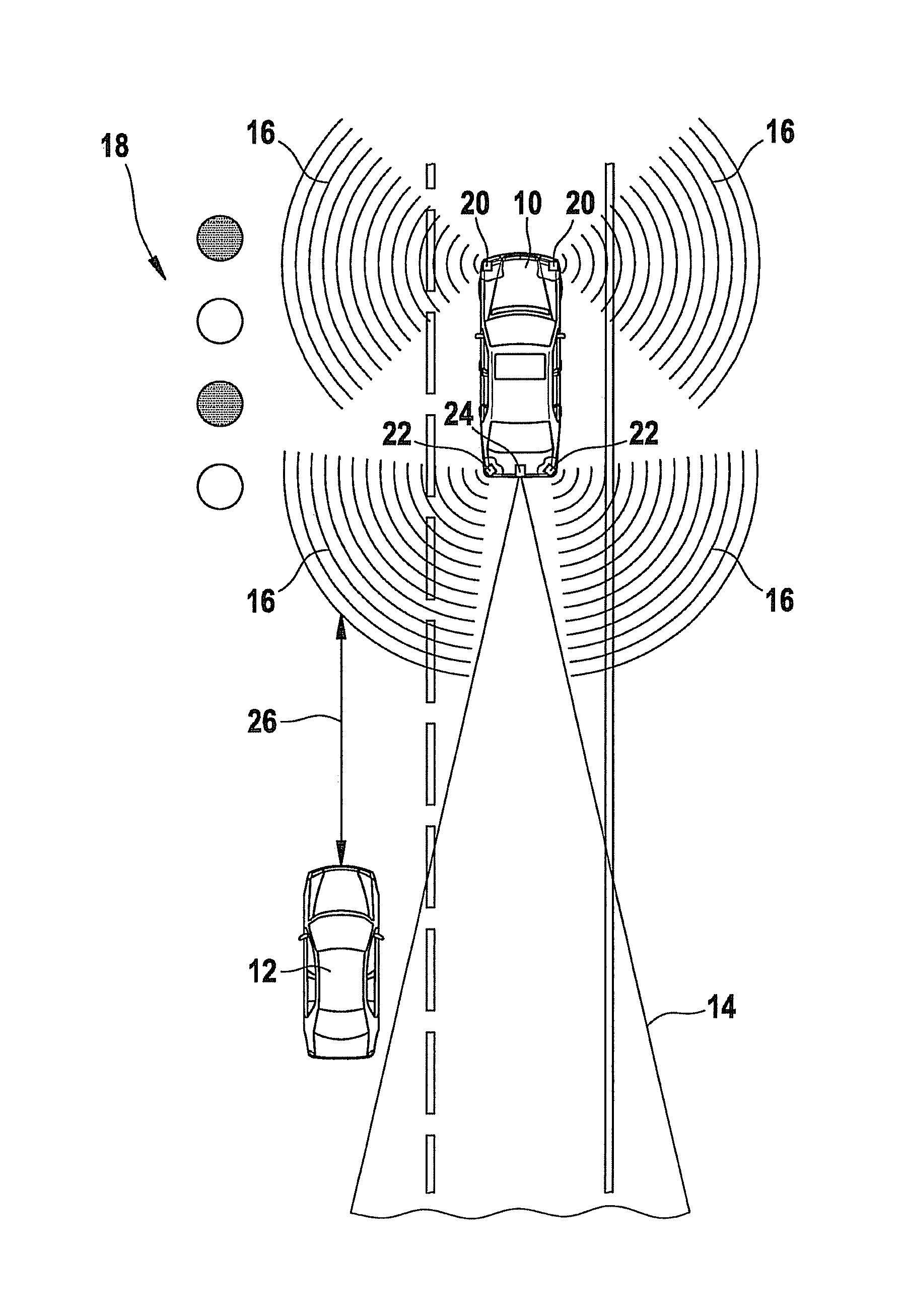
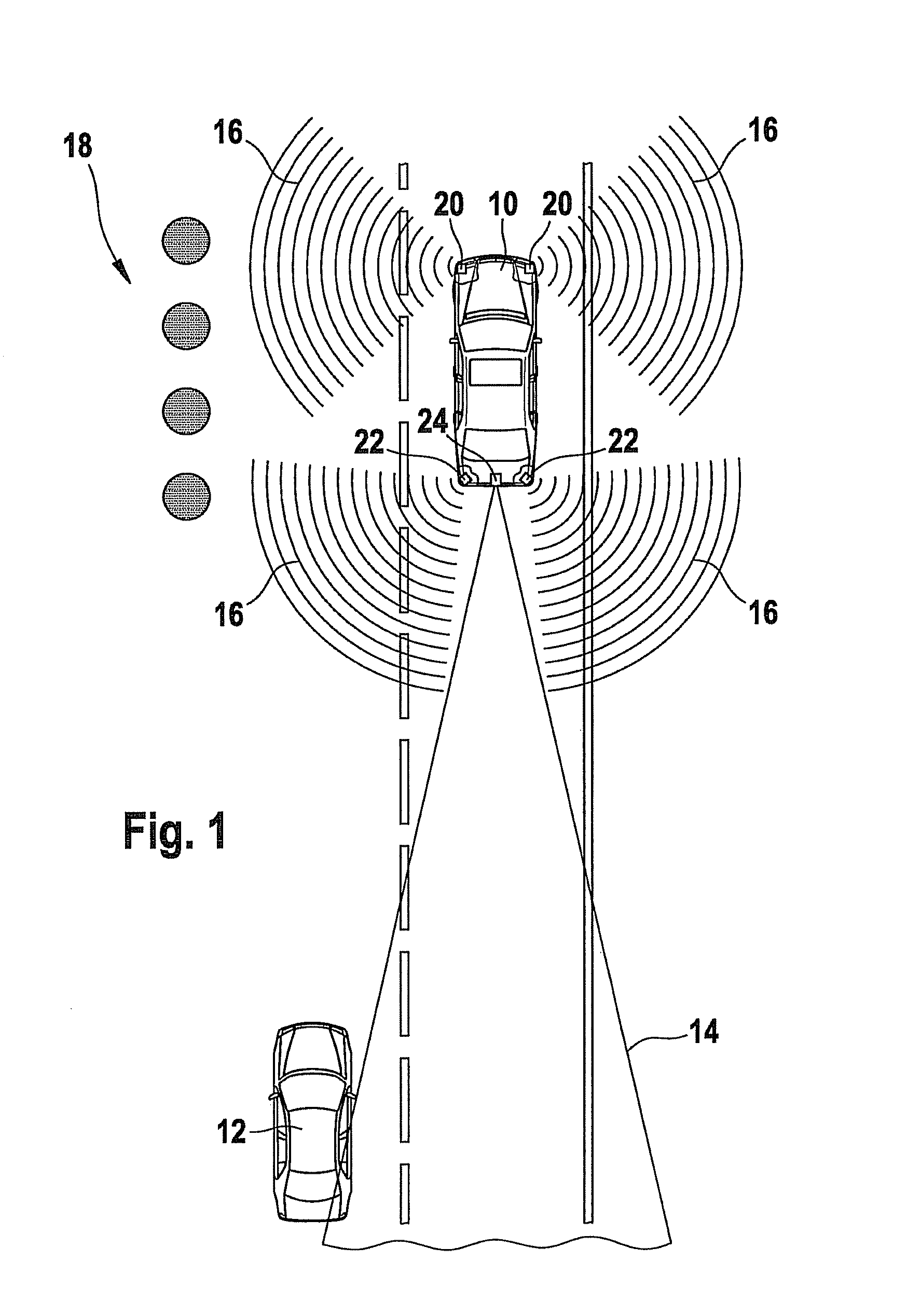
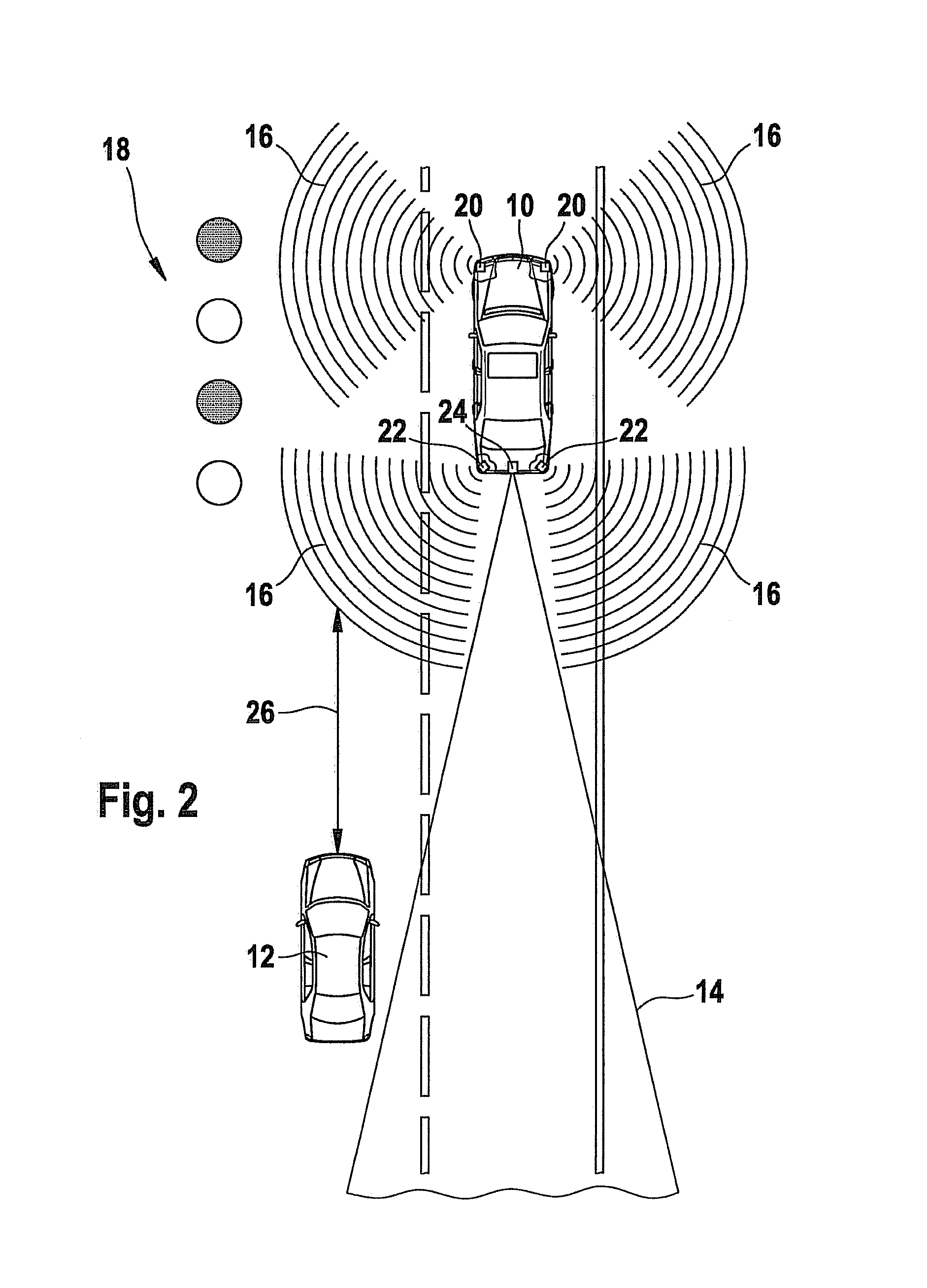
[0023]Example embodiments of the present invention are explained in more detail below with reference to the figures.

[0024]FIGS. 1 through 4 show the sequence of a typical traffic situation, in this case a passing maneuver. The figures show a first vehicle or ego vehicle 10, and a second vehicle or target vehicle 12. Target vehicle 12 is overtaking ego vehicle 10 whose blind spot region is being monitored. Ego vehicle 10 is equipped with a number of sensors for this purpose. For example, a long range 14 is monitored with the aid of radar or video, and a near range 16 is monitored with the aid of one or a plurality of ultrasonic sensors. Four signal lights 18, which emit an optical signal, are provided to warn the driver of ego vehicle 10. In addition, an acoustic signal may be output as well.

[0025]The method for blind spot monitoring is to warn the driver as soon as an object is located within the blind spot region of ego vehicle 10. However, if this were done all the time, then the ...


PUM


Abstract

A method is used for detecting the environment of a vehicle and utilizes a number of sensors, the sensors having different detection ranges, and a transition of an object between two detection ranges is bridged by prediction by using a handover algorithm.

Description

FIELD OF THE INVENTION[0001]The present invention relates to a method for detecting an environment of a vehicle, a system for executing the method, as well as to a computer program and a computer program product.BACKGROUND INFORMATION[0002]Lane-change assistants, as they are commonly referred to, which are used to warn a driver of an approaching vehicle, in particular one approaching from behind, are generally known. In this context it is especially important to alert the driver to vehicles located in the blind spot of the own vehicle. With planar rearview mirrors, this blind spot or blind spot region of the vehicle results to the left and right rear for the driver, to the side of the vehicle. If a vehicle is overtaken, the driver of the overtaken vehicle is unable to see the overtaking vehicle for a few seconds unless he looks over his shoulder. Although mandatory when turning and when changing lanes, this particular glance over the shoulder is often omitted, especially also on hig...

Claims


Application Information

Patent Timeline
Patent Type & Authority Patents(United States)
IPC IPC(8): B60Q1/00
CPCB60Q9/008B60W40/04
Inventor LEE, WEI-CHIA
Owner ROBERT BOSCH GMBH
Why Eureka
Try Eureka