
Slot antenna within existing device component

a technology of slot antenna and device component, which is applied in the direction of independent non-interfering antenna combination, substation equipment, transmission, etc., can solve the problems of narrow bandwidth and inconvenient use of single slot antenna in some wireless network applications, and achieve the effect of reducing the number of slot antennas

Active Publication Date: 2013-07-16
AMAZON TECH INC
View PDF65 Cites 54 Cited by
  • Summary
  • Abstract
  • Description
  • Claims
  • Application Information

AI Technical Summary

Benefits of technology

The patent text describes a new design for user devices that allows for improved antenna performance. The invention involves placing the antenna on a separate component that is housed within the device, rather than on the display itself. This change in design helps to avoid increasing the thickness of the device and allows for the use of a wider range of antenna frequencies. The patent describes various embodiments of the new design, including the use of a slot antenna or a metallic support member to hold the display. The technical effect of this invention is improved antenna performance in user devices, allowing for better wireless network connectivity and reduced thickness of the device.

Problems solved by technology

The slot antennas, having single slot openings, however, are typically considered to have a narrow bandwidth due to the discontinuities of the current flow within the limited space of the slot opening.
Since single slot antennas typically have a narrow bandwidth, single slot antennas may not be suitable for some wireless network applications, such as 3G applications.

Method used


Image

  • Slot antenna within existing device component
  • Slot antenna within existing device component
  • Slot antenna within existing device component

Examples


Embodiment Construction

[0037]A user device having a multi-band aperture antenna formed in metallic material of a structural member is described. In addition, a user device having a non-radiating exciter operatively coupled to feed an antenna is described. The user device may be any content rendering device that includes a wireless modem for connecting the user device to a network. Examples of such user devices include electronic book readers, cellular telephones, personal digital assistants (PDAs), portable media players, tablet computers, netbooks, and the like.

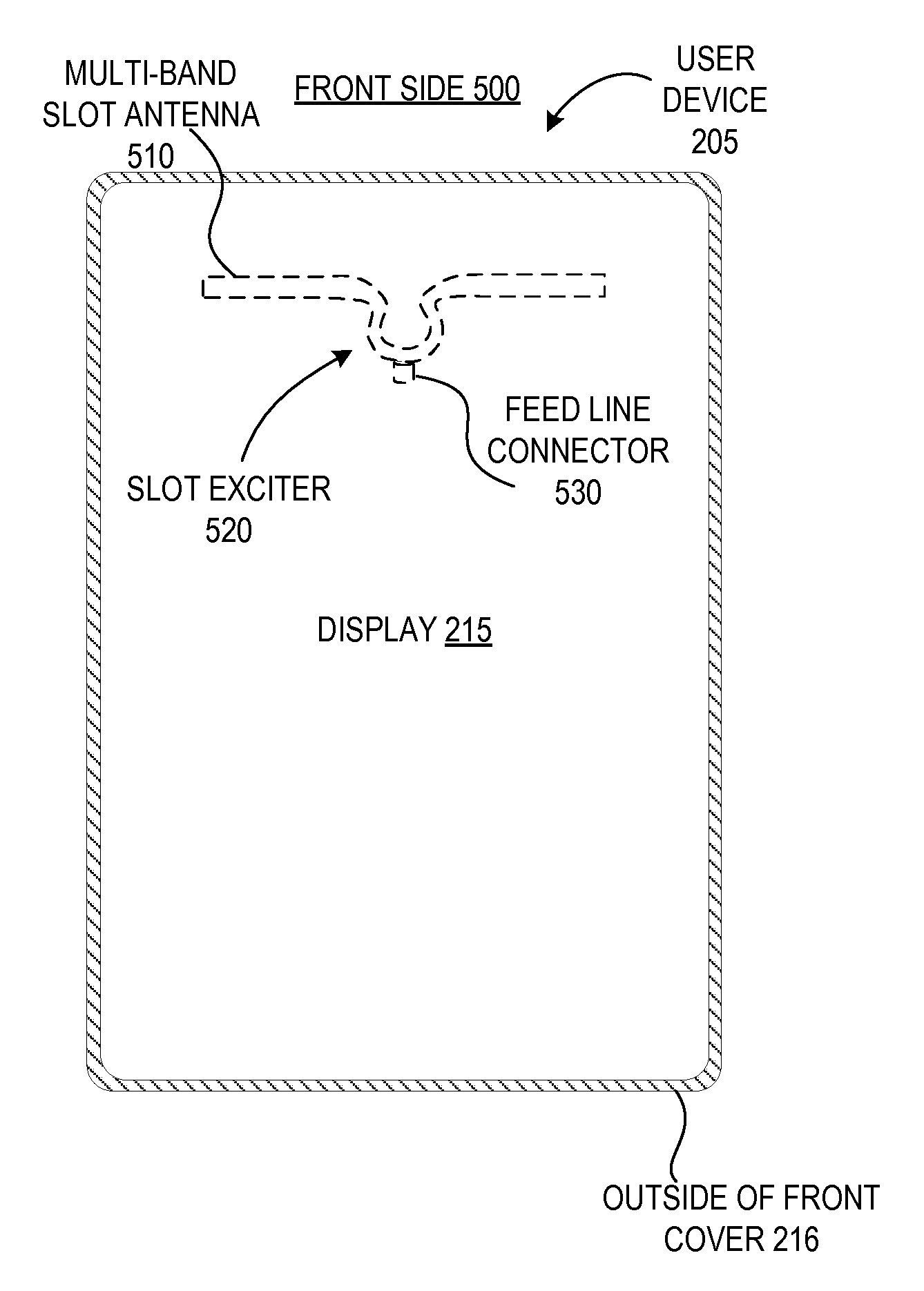
[0038]In one embodiment, a user device includes an antenna to radiate electromagnetic energy and a non-radiating exciter operatively coupled to feed the antenna. The non-radiating exciter may be physically coupled to, or physically separated from, the antenna. In one embodiment, the antenna is a multi-band aperture antenna. The multi-band aperture antenna may be a slot antenna, a plate inverted-F antenna (PIFA), a slot loop antenna, a multi-band s...


PUM


Abstract

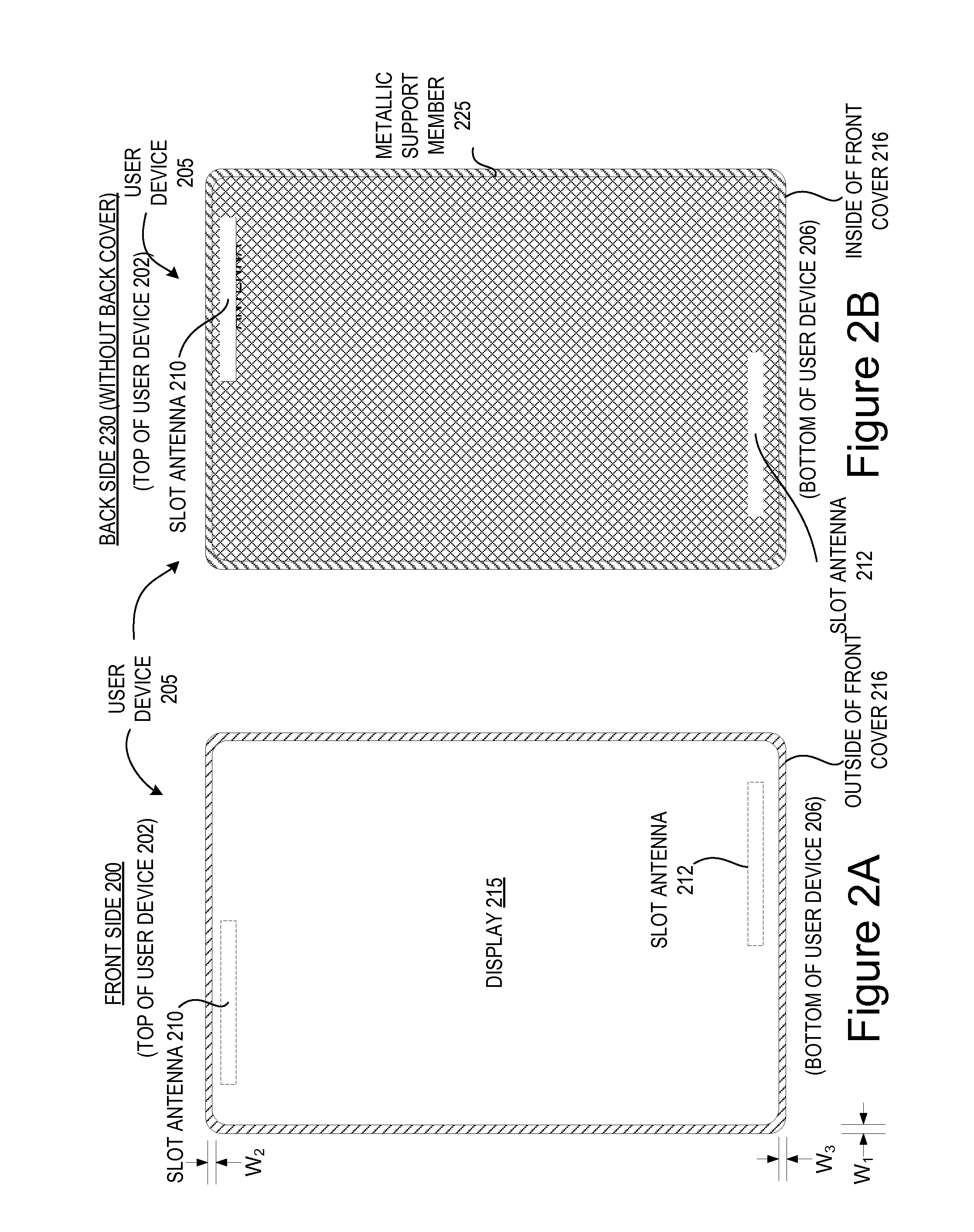
A user device having a slot antenna formed in metallic material of a structural member is described.

Description

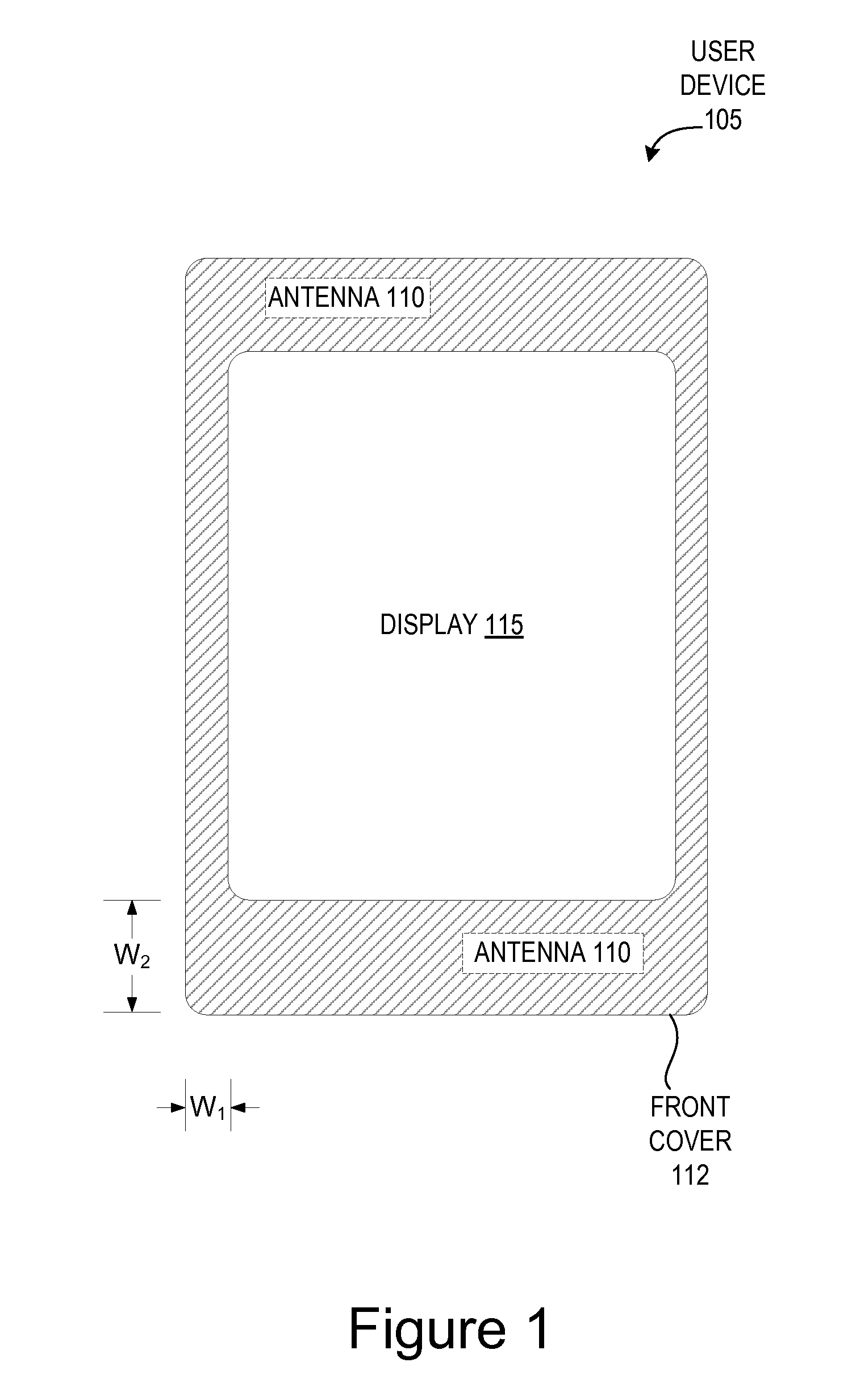
RELATED APPLICATIONS[0001]This application is related to co-pending U.S. application Ser. No. 12 / 858,225, entitled “Antenna with an Exciter,” filed Aug. 17, 2010, which is incorporated herein by reference.BACKGROUND OF THE INVENTION[0002]A large and growing population of users enjoy entertainment through the consumption of digital media items, such as music, movies, images, electronic books, and so on. Users employ various electronic devices to consume such media items. Among these electronic devices are electronic book readers, cellular telephones, personal digital assistants (PDAs), portable media players, tablet computers, netbooks, and the like. These electronic devices wirelessly communicate with a communications infrastructure to enable the consumption of the digital media items.[0003]FIG. 1 illustrates a front side of a conventional user device 105 having a display 115. The user device 105 includes an antenna 110 disposed within a housing of the user device and above or below...

Claims


Application Information

Patent Timeline
Patent Type & Authority Patents(United States)
IPC IPC(8): H04M1/00
CPCH01Q1/243H01Q1/44H01Q5/378H01Q13/106H01Q21/28H01Q9/0421
Inventor DOU, WEIPINGBOWEN, JAMES SAMUEL
Owner AMAZON TECH INC
Learn More