
Self-calibration method for electric power steering system

a self-calibration and electric power steering technology, applied in the direction of steering initiation, instruments, vessel construction, etc., can solve the problems of hydraulic piping that hydraulic fluid is likely to leak from hydraulic piping, and hydraulic piping is usually very complicated, so as to promote the robustness and performance of the eps system and stable steering sense of the driver

Active Publication Date: 2013-07-09
AUTOMOTIVE RES & TESTING CENT
View PDF10 Cites 2 Cited by
  • Summary
  • Abstract
  • Description
  • Claims
  • Application Information

AI Technical Summary

Benefits of technology

The present invention provides a self-calibration method for an electric power steering system. The method allows for self-calibration of sensors to prevent signal distortion, which improves the driver's steering sensory experience and enhances the performance and robustness of the EPS system. Additionally, the method uses a signal offset compensation tactic to increase accuracy of sensors, further improving the performance and reliability of the EPS system. The conventional technology requires a lot of time and labor to calibrate sensors, meaning the present invention offers a more efficient solution to this problem.

Problems solved by technology

However, hydraulic fluid is likely to leak from hydraulic piping.
Further, hydraulic fluid is likely to heat up and denature because of friction between hydraulic fluid and piping.
Besides, hydraulic piping is usually very complicated.
Because of long-term use or displacement of installation positions, sensors will drift from their normal states and generates signals having slight errors.
Environmental factors, such as temperature, or instable power supply, may cause erroneous auxiliary torque or discontinuous auxiliary force and affect the performance of the EPS system.
In mass production, the total time and manpower spent in normalizing the sensors of all the vehicles is very considerable.
Therefore, how to overcome sensor accuracy degradation caused by power supply variation and promote robustness of EPS systems is a problem the manufacturers desire to solve.

Method used


Image

  • Self-calibration method for electric power steering system
  • Self-calibration method for electric power steering system
  • Self-calibration method for electric power steering system

Examples


Embodiment Construction

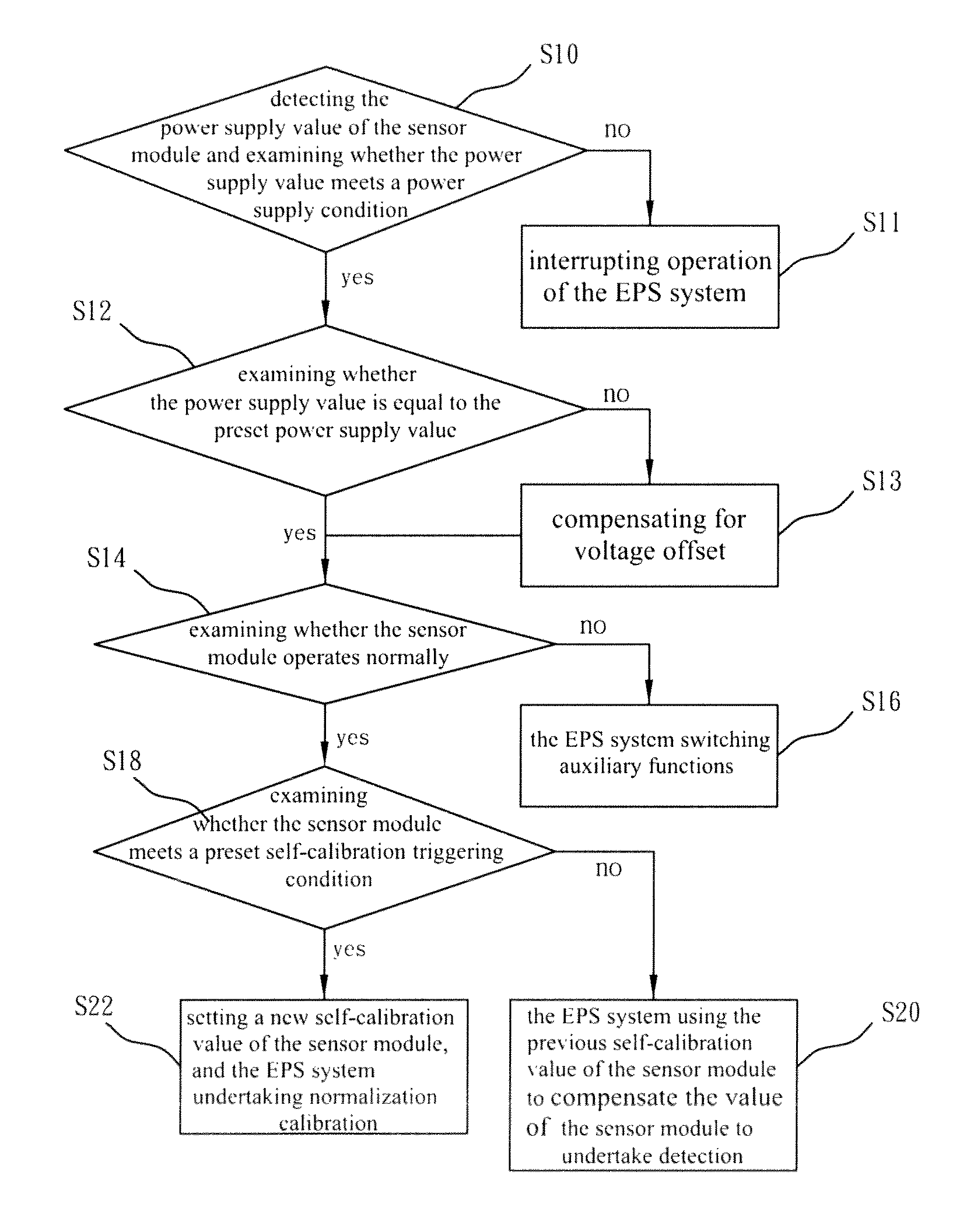
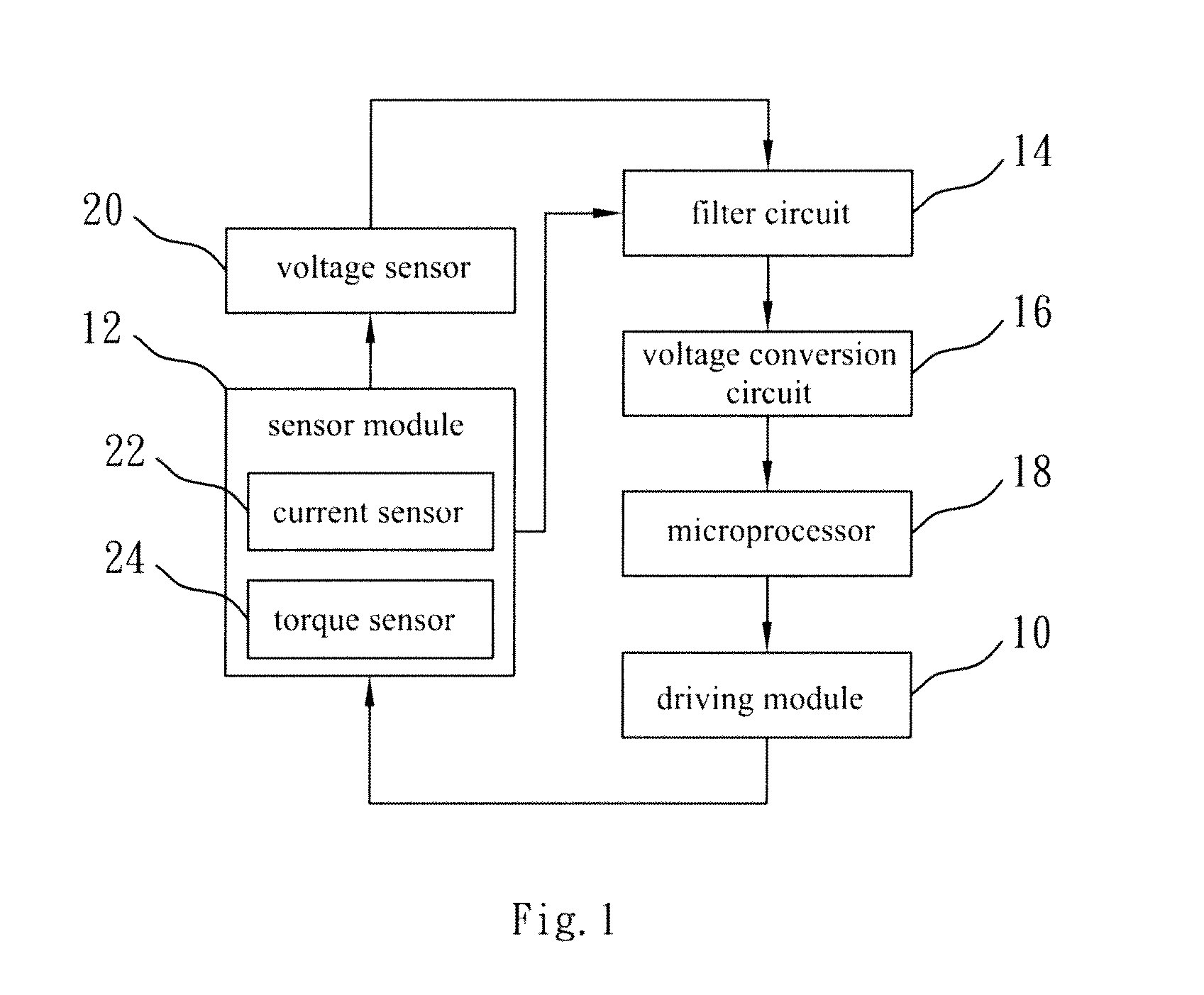
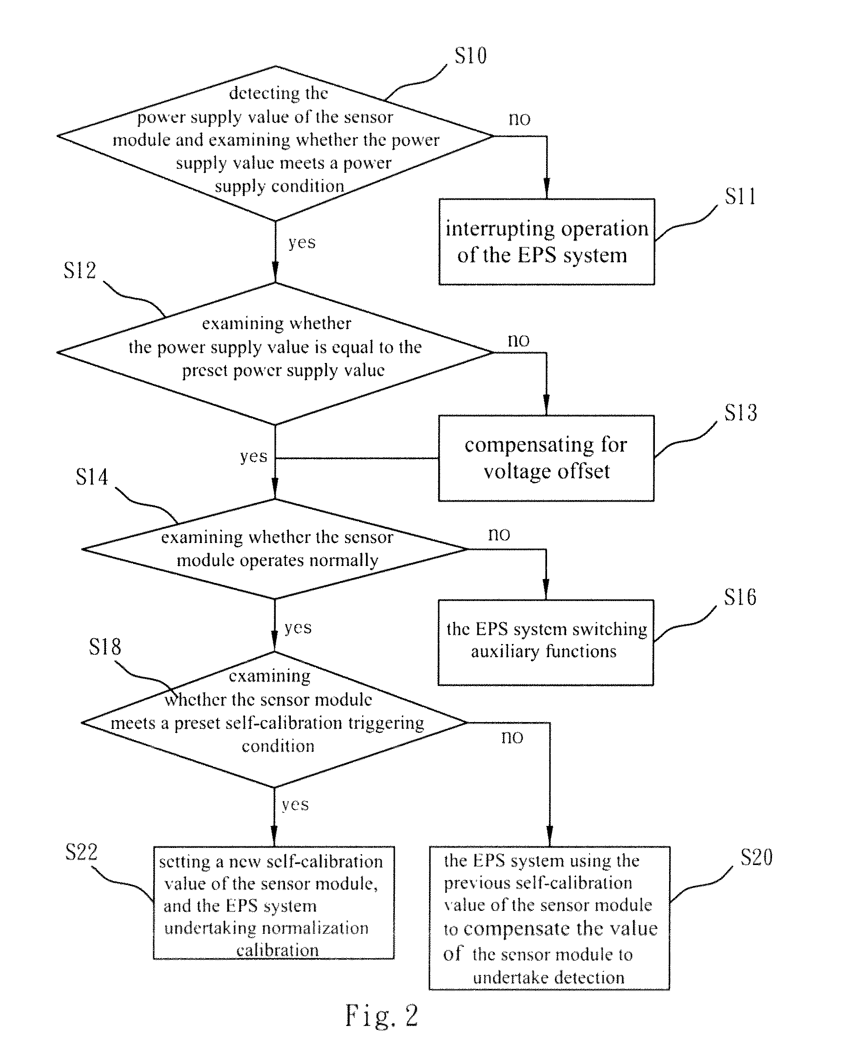
[0023]In the present invention, the EPS system applies to a vehicle. The variation or abnormality of the power supply of any sensor of the EPS system may cause distortion of sensor signals or false actions of the EPS system. In order to avoid the abovementioned problems, the present invention addresses improving safety and robustness of the EPS system. Refer to FIG. 1 and FIG. 2. FIG. 1 is a block diagram schematically showing the architecture of an EPS system according to one embodiment of the present invention. FIG. 2 is a flow chart of a self-calibration method for an EPS system according to one embodiment of the present invention. The EPS system of the present invention comprises a driving module 10, at least one sensor module 12, a filter circuit 14, a voltage conversion circuit 16 and a microprocessor 18. The driving module 10 is coupled to a vehicle steering system and outputs torque to assist the vehicle driver in rotating the steering wheel. The driving module 10 includes a...


PUM


Abstract

The present invention discloses a self-calibration method for an electric power steering system, which can self-calibrate the sensors to a normalized state to prevent from signal distortion, whereby to maintain stable steering sense of the driver and promote robustness and performance of the EPS system. The self-calibration method includes a signal offset compensation tactic and a zero-point signal self-calibration tactic. The present invention determines whether to undertake self-calibration according to judgement tactics, including a sensor power supply judgement tactic, a sensor correctness judgement tactic, and a self-calibration triggering condition. The self-calibration method can increase the correctness of sensors, maintain the original steering-assisting function and promote robustness of the EPS system.

Description

BACKGROUND OF THE INVENTION[0001]1. Field of the Invention[0002]The present invention relates to a self-calibration method for an electric power steering system, particularly to an EPS self-calibration method normalizing signals of sensors.[0003]2. Description of the Related Art[0004]Before, a powerful and smooth-operation HPS (Hydraulic Power Steering) system was used as an auxiliary power source to lessen the driver's burden of operating the steering wheel. However, hydraulic fluid is likely to leak from hydraulic piping. Further, hydraulic fluid is likely to heat up and denature because of friction between hydraulic fluid and piping. Besides, hydraulic piping is usually very complicated. Thus, the EPS (Electric Power Steering) system has gradually replaced the conventional HPS system.[0005]Compared with the HPS system using a hydraulic pump, an oil tank, hydraulic piping and a belt-pulley system that transmits engine power to drive the pump, the EPS system is implemented by elect...

Claims


Application Information

Patent Timeline
Patent Type & Authority Patents(United States)
IPC IPC(8): A01B69/00
CPCB62D5/0457
Inventor HSU, JIN-YANYEH, CHIH-JUNGHU, TSUNG-HSIENCHIU, HSIEN-CHANG
Owner AUTOMOTIVE RES & TESTING CENT
Learn More