Membrane-electrode assembly, fuel cell, and fuel cell system
a technology of membrane electrolectrodes and fuel cells, applied in the field of fuel cells, can solve the problems of high voltage drop rate, and achieve the effect of preventing the deterioration of the conductivity and gas diffusibility
- Summary
- Abstract
- Description
- Claims
- Application Information
AI Technical Summary
Benefits of technology
Problems solved by technology
Method used
Image
Examples
example embodiment 1
[0082](Example Embodiment 1)
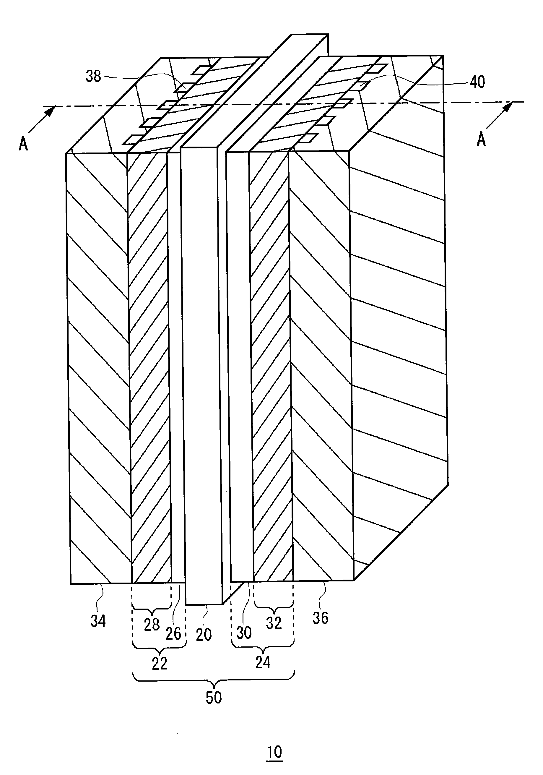
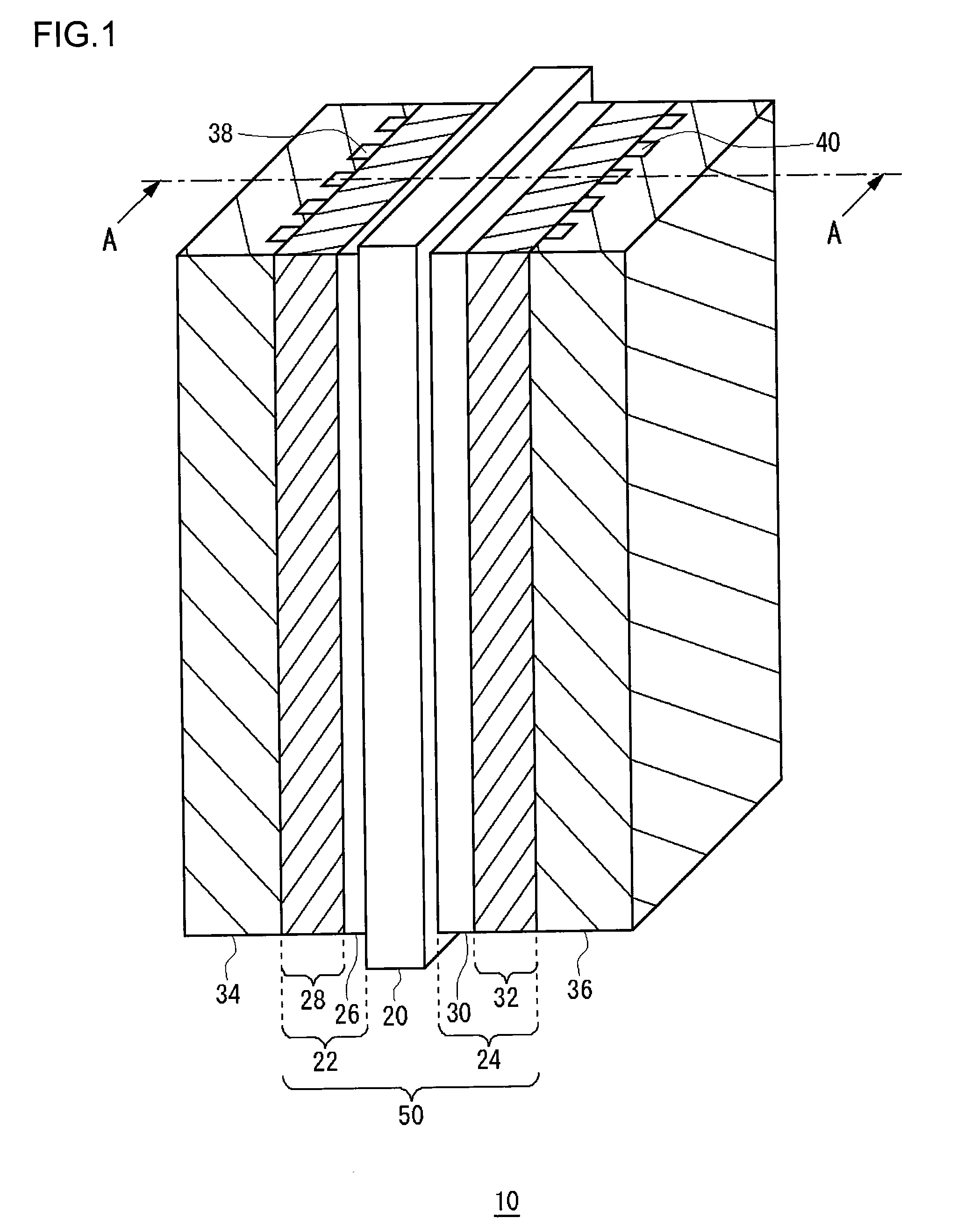
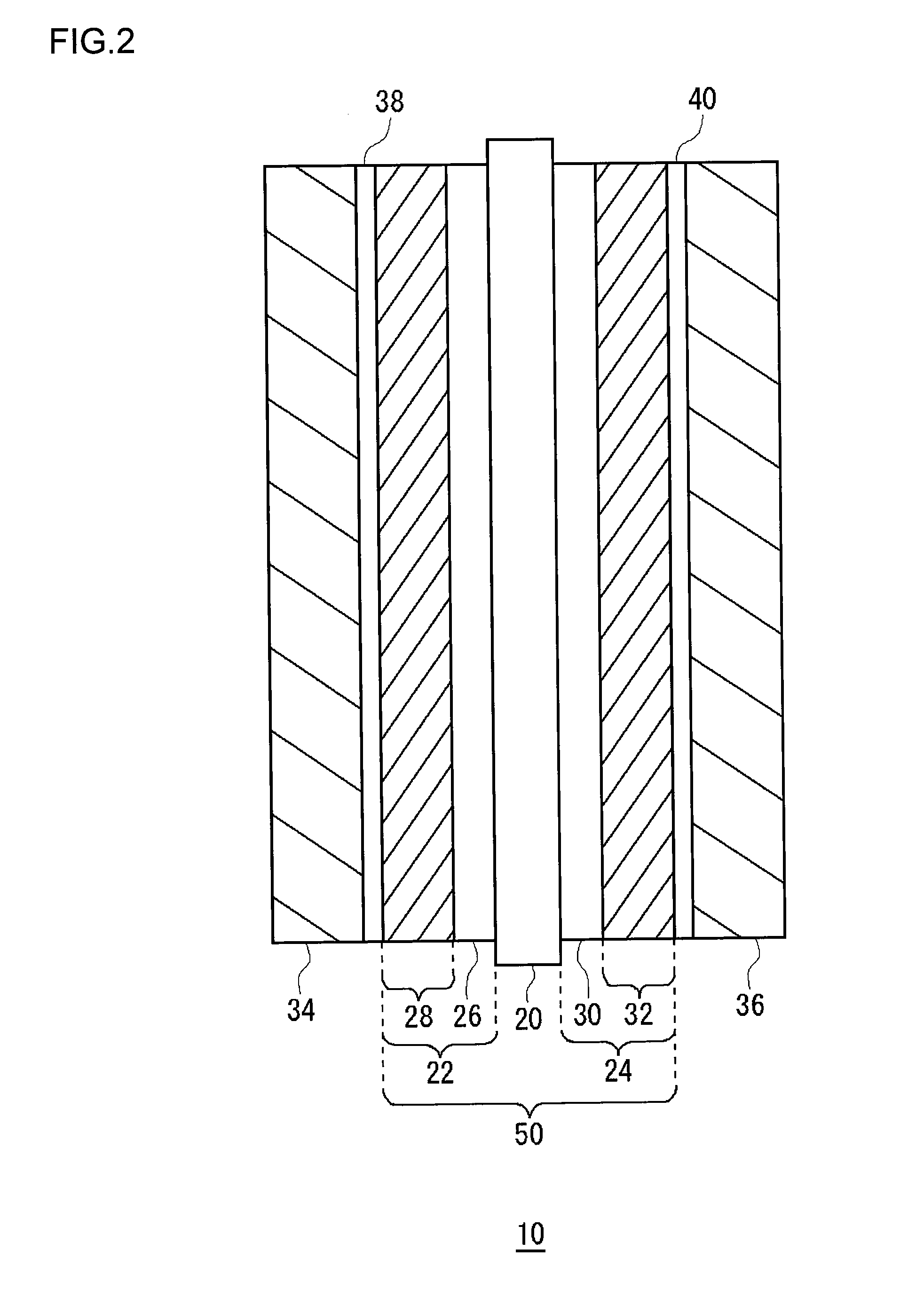
[0083]A membrane electrode assembly according to a first example embodiment was made by the above-described method for manufacturing a membrane electrode assembly. The mesoporous silica used was TMPS-4-1, as shown in FIG. 3, whose average pore diameter was 4.0 nm and average particle diameter was 3.0 μm. The amount of mesoporous silica added was 120 mg / cm2. Using a membrane electrode assembly according to the first example embodiment, a temperature fluctuation endurance test was conducted on a single cell of 25 cm2. The conditions for power generation were as follows.
[0084]Current density: 0.3 A / cm2
[0085]Anode gas: Hydrogen
[0086]Cathode gas: Air
[0087]Fuel utilization: 75%
[0088]Air utilization: 55%
[0089]For a cell temperature of 80° C., the humidifying temperature was changed in cycles of about one hour each between 71° C. and 76° C. for both the anode and the cathode. The cell voltage values (V) found in the endurance test of 4000 hours are shown in Tabl...
example embodiment 2
[0091](Example Embodiment 2)
[0092]A membrane electrode assembly according to a second example embodiment was made by the above-described method for manufacturing a membrane electrode assembly. Under the humidifying conditions of 53 to 60° C. for both the anode gas and cathode gas, which are extremely low humidifying conditions, the relative humidity within the cell is within a range of 30 to 100% RH for the humidifying temperature of 53° C. and within a range of 42 to 100% RH for the humidifying temperature of 60° C. Accordingly, in this example embodiment, the mesoporous humidity control agent used as one suited to the extremely low humidifying conditions was a mixture of the mesoporous silica (TMPS-1.5-1 made by Taiyo Kagaku Co., Ltd.) whose average pore diameter was 1.5 nm and the mesoporous silica (TMPS-4-1 made by Taiyo Kagaku Co., Ltd.) whose average pore diameter was 4.0 nm (see FIG. 3). The mesoporous silica used in the second example embodiment was such that the particle di...
example embodiment 3
[0102](Example Embodiment 3)
[0103]FIG. 4 is a diagram showing a schema of a fuel cell system using a membrane electrode assembly according to a third example embodiment.
[0104]A hydrocarbon-based gas, such as natural gas or LPG, is supplied to a reformer 110 as a raw fuel for reforming. Also supplied to the reformer 110 are a water-treated clean water as reforming water and air from the outside. The reformer 110 performs a steam reforming of the raw fuel using the reforming water, thereby generating a reformed gas rich in hydrogen gas.
[0105]The reformed gas generated by the reformer 110 is supplied to a CO transformer 120, where CO is transformed into hydrogen by a shift reaction. This will reduce the CO concentration to 0.5% or below. Further, at a CO remover 130, the CO concentration is reduced to about 10 ppm through a CO oxidation reaction using a CO selective removal catalyst. The reformed gas whose CO concentration has been reduced by the CO remover 130 is supplied to the anode...
PUM
| Property | Measurement | Unit |
|---|---|---|
| pore diameter | aaaaa | aaaaa |
| temperature | aaaaa | aaaaa |
| thickness | aaaaa | aaaaa |
Abstract
Description
Claims
Application Information
 - R&D
- Intellectual Property
- Life Sciences
- Materials
- Tech Scout
- Unparalleled Data Quality
- Higher Quality Content
- 60% Fewer Hallucinations
Browse by: Latest US Patents, China's latest patents, Technical Efficacy Thesaurus, Application Domain, Technology Topic, Popular Technical Reports.
© 2025 PatSnap. All rights reserved.Legal|Privacy policy|Modern Slavery Act Transparency Statement|Sitemap|About US| Contact US: help@patsnap.com


