Valve train device
a technology of valve train and valve body, which is applied in the direction of non-mechanical valves, electrical control, magnetic bodies, etc., can solve the problems of low error-proneness and other problems
- Summary
- Abstract
- Description
- Claims
- Application Information
AI Technical Summary
Benefits of technology
Problems solved by technology
Method used
Image
Examples
Embodiment Construction
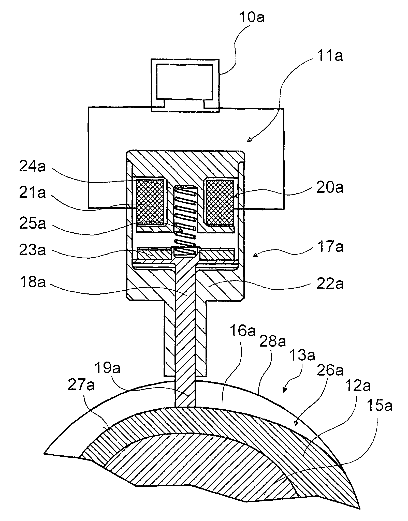
[0022]FIG. 1 shows a control device for a valve train of an internal combustion engine. The valve train control device comprises a cam element 12a located non-rotatably but axially movably with respect to a camshaft 15a. The cam element 12a is displaced by means of a switching unit 11a and a shift gate 13a. The shift gate 13a has a gate track 16a in the form of a groove.
[0023]The switching unit 11a comprises an actuator 17a and a switching element 18a. The switching element 18a is in the form of a switching pin 19a which is extended in a switching position of the switching element 18a. In the switching position, the switching pin 19a engages the gate track 16a of the shift gate 13a.
[0024]The actuator 17a which moves the switching element 18a, comprises a solenoid unit 20a. The solenoid unit 20a comprises a coil 21a located in a stator 22a of the solenoid unit. The coil 21a can generate a magnetic field which interacts with a permanent magnet 23a located in the switching element 18a...
PUM
 Abstract
Description
Claims
Application Information
 - R&D
- Intellectual Property
- Life Sciences
- Materials
- Tech Scout
- Unparalleled Data Quality
- Higher Quality Content
- 60% Fewer Hallucinations
Browse by: Latest US Patents, China's latest patents, Technical Efficacy Thesaurus, Application Domain, Technology Topic, Popular Technical Reports.
© 2025 PatSnap. All rights reserved.Legal|Privacy policy|Modern Slavery Act Transparency Statement|Sitemap|About US| Contact US: help@patsnap.com


