
Multiple aperture ultrasound array alignment fixture

an alignment fixture and multi-aperture technology, applied in the field of imaging techniques used in medicine, can solve the problems of poor lateral resolution, small aperture, and use of ultrasonic imaging for medical purposes

Active Publication Date: 2013-06-25
MAUI IMAGING
View PDF208 Cites 42 Cited by
  • Summary
  • Abstract
  • Description
  • Claims
  • Application Information

AI Technical Summary

Benefits of technology

The present invention relates to a system for measuring and aligning the positions of transducer elements in a multi-aperture ultrasound probe. The system includes an alignment assembly for holding the transducer elements, a test block, an ultrasonic sensor, and a controller for evaluating data from the ultrasonic sensor and providing calibration data. The system can automatically align the transducer elements based on the calibration data or allow for manual alignment. The system can also include a graphical user interface for displaying the calibration data. The technical effects of the invention include improved accuracy and efficiency in measuring and aligning the positions of transducer elements in a multi-aperture ultrasound probe.

Problems solved by technology

This design configuration lies at the heart of one of the most significant limitations in the use of ultrasonic imaging for medical purposes; namely, poor lateral resolution.
Theoretically, the lateral resolution could be improved by increasing the aperture of the ultrasonic probe, but the practical problems involved with aperture size increase have kept apertures small and lateral resolution poor.
For scanners intended for abdominal and other use, the limitation on aperture size is not so obvious, but it is a serious limitation nevertheless.
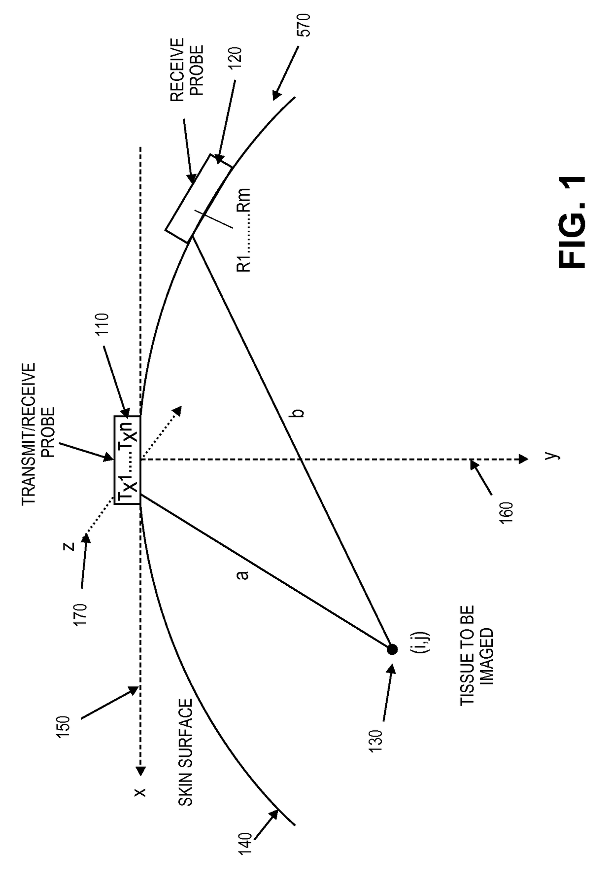
The problem is that it is difficult to know the exact position of the elements of a large apparatus with multiple and separate physical points of contact (“footprints”) on the patient.

Method used


Image

  • Multiple aperture ultrasound array alignment fixture
  • Multiple aperture ultrasound array alignment fixture
  • Multiple aperture ultrasound array alignment fixture

Examples


Embodiment Construction

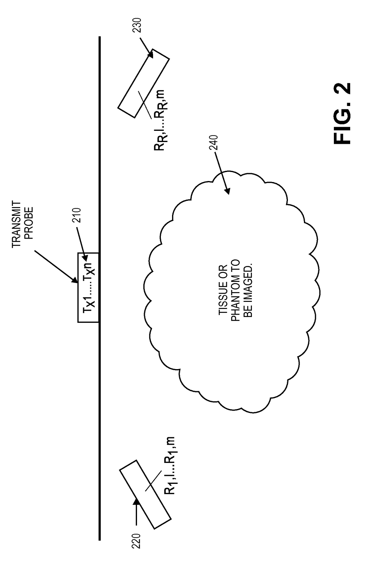
[0080]A Multiple Aperture Ultrasound Imaging (MAUI) Probe or Transducer can vary by medical application. That is, a general radiology probe can contain multiple transducers that maintain separate physical points of contact with the patient's skin, allowing multiple physical apertures. A cardiac probe may contain as few as two transmitters and receivers where the probe fits simultaneously between two or more intercostal spaces. An intracavity version of the probe, will space transmit and receive transducers along the length of the wand, while an intravenous version will allow transducers to be located on the distal length the catheter and separated by mere millimeters. In all cases, operation of multiple aperture ultrasound transducers can be greatly enhanced if they are constructed so that the elements of the arrays are aligned within a particular scan plane.

[0081]One aspect of the invention solves the problem of constructing a multiple aperture probe that functionally houses multip...


PUM

PropertyMeasurementUnit
/10 wavelengthaaaaaaaaaa
depthaaaaaaaaaa
D2 distancesaaaaaaaaaa

Abstract

Increasing the effective aperture of an ultrasound imaging probe by including more than one probe head and using the elements of all of the probes to render an image can greatly improve the lateral resolution of the generated image. In order to render an image, the relative positions of all of the elements must be known precisely. A calibration fixture is described in which the probe assembly to be calibrated is placed above a test block and transmits ultrasonic pulses through the test block to an ultrasonic sensor. As the ultrasonic pulses are transmitted though some or all of the elements in the probe to be tested, the differential transit times of arrival of the waveform are measured precisely. From these measurements the relative positions of the probe elements can be computed and the probe can be aligned.

Description

CROSS REFERENCE TO RELATED APPLICATIONS[0001]This application claims the benefit of U.S. Provisional Patent Application No. 61 / 169,200, filed Apr. 14, 2009, titled “ALIGNMENT AND FIXTURING OF A UNIVERSAL MULTIPLE APERTURE MEDICAL ULTRASOUND TRANSDUCER”, which is herein incorporated by reference.[0002]This application is related to U.S. patent application Ser. No. 11 / 532,013, filed Sep. 14, 2006, now U.S. Pat. No. 8,105,239, which claims priority to U.S. Provisional Patent Application No. 60 / 765,887, filed Feb. 6, 2006, and is related to U.S. patent application Ser. No. 11 / 865,501, filed Oct. 1, 2007, which claims priority to U.S. Provisional Patent Application No. 60 / 862,951, filed Oct. 25, 2006, and U.S. Provisional Patent Application No. 60 / 940,261, filed May 25, 2007; and is related to U.S. Provisional Patent Application Nos. 61 / 169,251, filed Apr. 14, 2009, and 61 / 169,221, filed Apr. 14, 2009; all of which are herein incorporated by reference.INCORPORATION BY REFERENCE[0003]All ...

Claims


Application Information

Patent Timeline
Patent Type & Authority Patents(United States)
IPC IPC(8): G01N29/00
CPCA61B8/00A61B8/4218G01S7/5205G01S15/8913A61B8/42A61B8/587A61B8/0883Y10T29/49778A61B8/4444A61B8/4477A61B8/4494G01N2291/106
Inventor SPECHT, DONALD F.BREWER, KENNETH D.SMITH, DAVID M.ADAM, SHARON L.LUNSFORD, JOHN P.
Owner MAUI IMAGING
Learn More