
Flight control system having a three control loop design

a control system and control loop technology, applied in adaptive control, distance measurement, instruments, etc., can solve the problems of increasing engineering hours, reducing the reliability of flight control systems, so as to increase the reliability of flight testing, increase the handling quality and performance, and increase the robustness of unmanned aircrafts

Active Publication Date: 2013-06-25
TEXTRON INNOVATIONS
View PDF7 Cites 31 Cited by
  • Summary
  • Abstract
  • Description
  • Claims
  • Application Information

AI Technical Summary

Benefits of technology

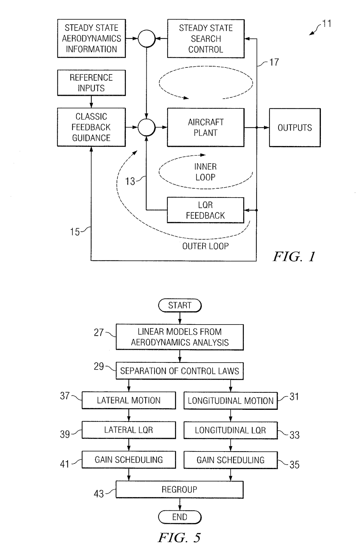
[0007]A flight control system is configured for controlling the flight of an aircraft utilizing a three control loop design to robustly increase system performance. An inner loop comprises an improved linear quadratic regulator (LQR) search method, and an outer loop comprises a classic feedback summary gain design. A third loop comprises a steady state trim search method.
[0008]The present invention includes significant benefits and advantages, including: (1) increasing handling qualities and performance for piloted aircrafts; (2) increasing robustness for unmanned aircrafts; (3) reducing flight test time; (4) reducing flight control law development time; (5) providing for easily applied intelligent portion for unmanned control; (6) providing for the system to be easily understood and implemented by engineers; and (7) using all advantages from classic feedback and modern control methods and eliminating their disadvantages.

Problems solved by technology

Control of an unstable aircraft flight system, such as a helicopter, has proven to be very challenging using classic feedback control laws.
Improvement of the system performances and maneuvers are limited, and robustness of the flight control system may not be considered in this method.
When the flight performance is not as desired, changing these gains takes time, which may delay flight testing and increase engineering hours.
The improved performance for this method is also limited, and robustness of the system is not guaranteed in this method.
This method does not lead to the development of sufficiently robust control laws.

Method used


Image

  • Flight control system having a three control loop design
  • Flight control system having a three control loop design
  • Flight control system having a three control loop design

Examples


Embodiment Construction

[0023]The present invention is directed to a three control loop flight control system configured for automatically controlling the flight of an aircraft. One purpose of the present invention is to make an open-loop unstable aircraft system stable by: (1) making the system stable first; (2) allowing the aircraft to be capably guided to any waypoint with any required airspeed; and (3) allowing the aircraft to save control effort for possible maneuvers.

[0024]The three control loop design of the present invention will robustly enlarge the stability of the aircraft control laws. Instead of using classic feedback control law, the present invention enhances the system by: (1) leaving the strongest portion of classic feedback control system; and (2) introducing two other control laws to handle the natural weakness of classic feedback control law. The present invention saves flight test periods and shortens the time required to design control laws. Use of the three control loops has been as ...


PUM


Abstract

A flight control system is configured for controlling the flight of an aircraft utilizing a three control loop design to robustly increase system performance. An inner loop comprises an improved linear quadratic regulator (LQR) search method, and an outer loop comprises a classic feedback summary gain design. A third loop comprises a steady state trim search method.

Description

TECHNICAL FIELD[0001]The present invention relates generally to the field of flight control systems for manned and unmanned aircraft and specifically to systems configured for robustly improving flight performance.DESCRIPTION OF THE PRIOR ART[0002]Control of an unstable aircraft flight system, such as a helicopter, has proven to be very challenging using classic feedback control laws. One method for controlling a helicopter employs purely classic feedback control laws, and this method requires a significant amount of flight testing to adjust individual gains to ensure the system's stability. In addition, flight quality depends upon adjustment of these gains and the natural design of the helicopter. Improvement of the system performances and maneuvers are limited, and robustness of the flight control system may not be considered in this method.[0003]Another method is classic feedback with optimal gain search. For this method, the individual optimal search algorithm needs to be manual...

Claims


Application Information

Patent Timeline
Patent Type & Authority Patents(United States)
IPC IPC(8): G06F19/00G01C22/00
CPCG05D1/101
Inventor SHUE, SHYHPYNG JACKSHILLINGS, JOHN J.
Owner TEXTRON INNOVATIONS
Learn More