
Fan

a technology of fan blades and fan blades, which is applied in the field of fans, can solve the problems of uneven or choppy air flow produced by the rotating blades of the fan, uncomfortable for users, and general uneven air flow, and achieve the effects of reducing carbon debris and emissions, lowering the centre of gravity of the fan, and less prone to falling over

Inactive Publication Date: 2013-06-25
DYSON TECH LTD
View PDF397 Cites 24 Cited by
  • Summary
  • Abstract
  • Description
  • Claims
  • Application Information

AI Technical Summary

Benefits of technology

The present invention is a fan assembly with a telescopic duct that supports the air outlet and conveys the air flow created by the fan assembly. The fan is powered by a DC brushless motor, which reduces friction and emissions. The base of the fan has a diffuser with spiral vanes that emits a spiraling air flow. The air flow is guided into the duct using a plurality of vanes and radial vanes. The fan is in the form of a bladeless fan assembly, which leads to a reduction in moving parts and complexity. The nozzle has an annular mouth with an inner and outer casing section that partially overlap, and a slot-shaped outlet. The nozzle also has spacers to maintain a uniform outlet width. The technical effects of the invention include improved stability, reduced noise, and improved air flow control.

Problems solved by technology

A disadvantage of this type of arrangement is that the air flow produced by the rotating blades of the fan is generally not uniform.
These variations result in the generation of an uneven or ‘choppy’ air flow which can be felt as a series of pulses of air and which can be uncomfortable for a user.
In a domestic environment it is undesirable for parts of the appliance to project outwardly, or for a user to be able to touch any moving parts, such as the blades.
Pedestal fans tend to have a cage surrounding the blades to prevent injury from contact with the rotating blades, but such caged parts can be difficult to clean.
This can render the pedestal fan prone to falling if accidentally knocked unless the pedestal is provided with a relatively wide or heavy base, which may be undesirable for a user.

Method used


Image

  • Fan
  • Fan
  • Fan

Examples


Embodiment Construction

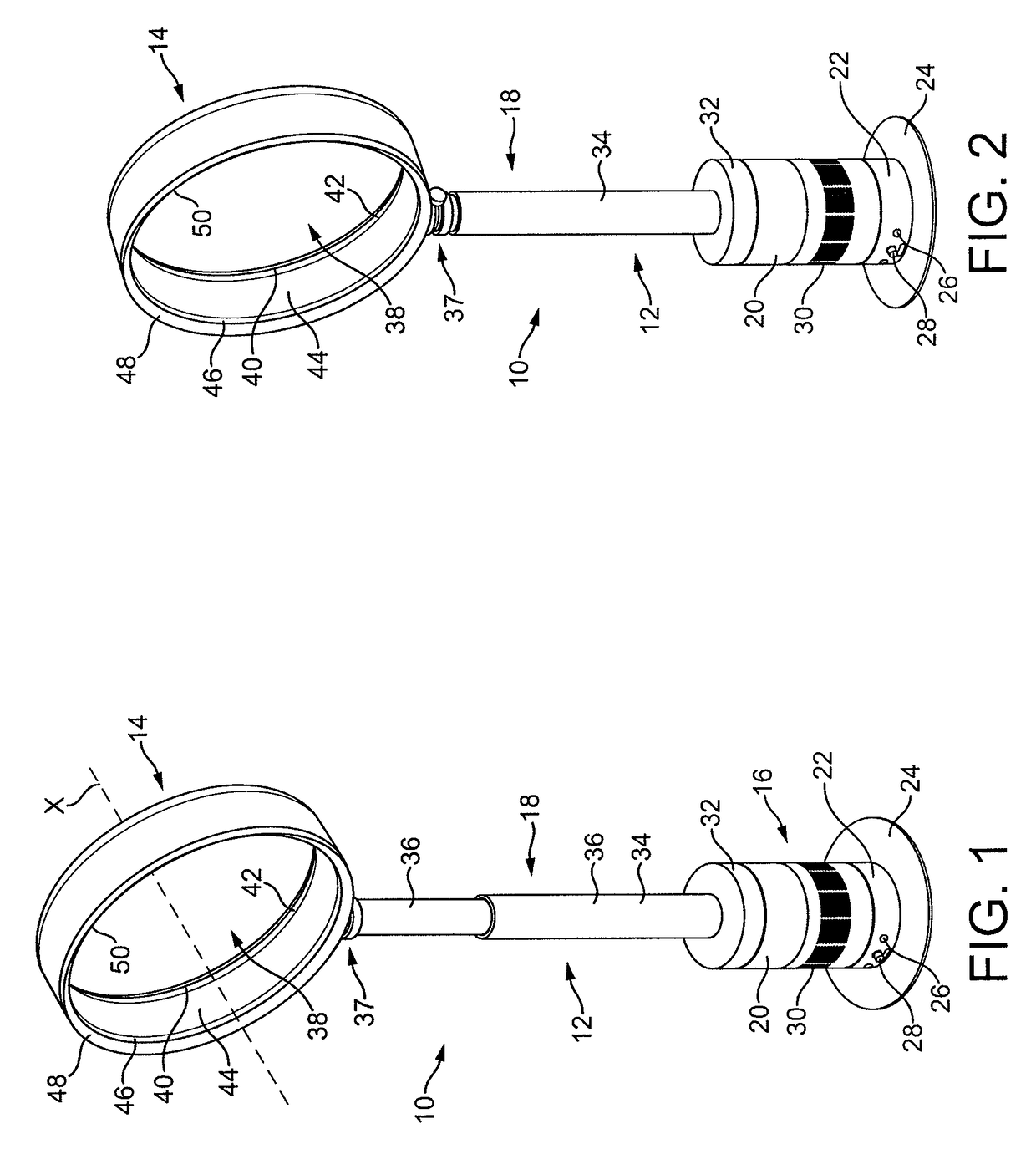
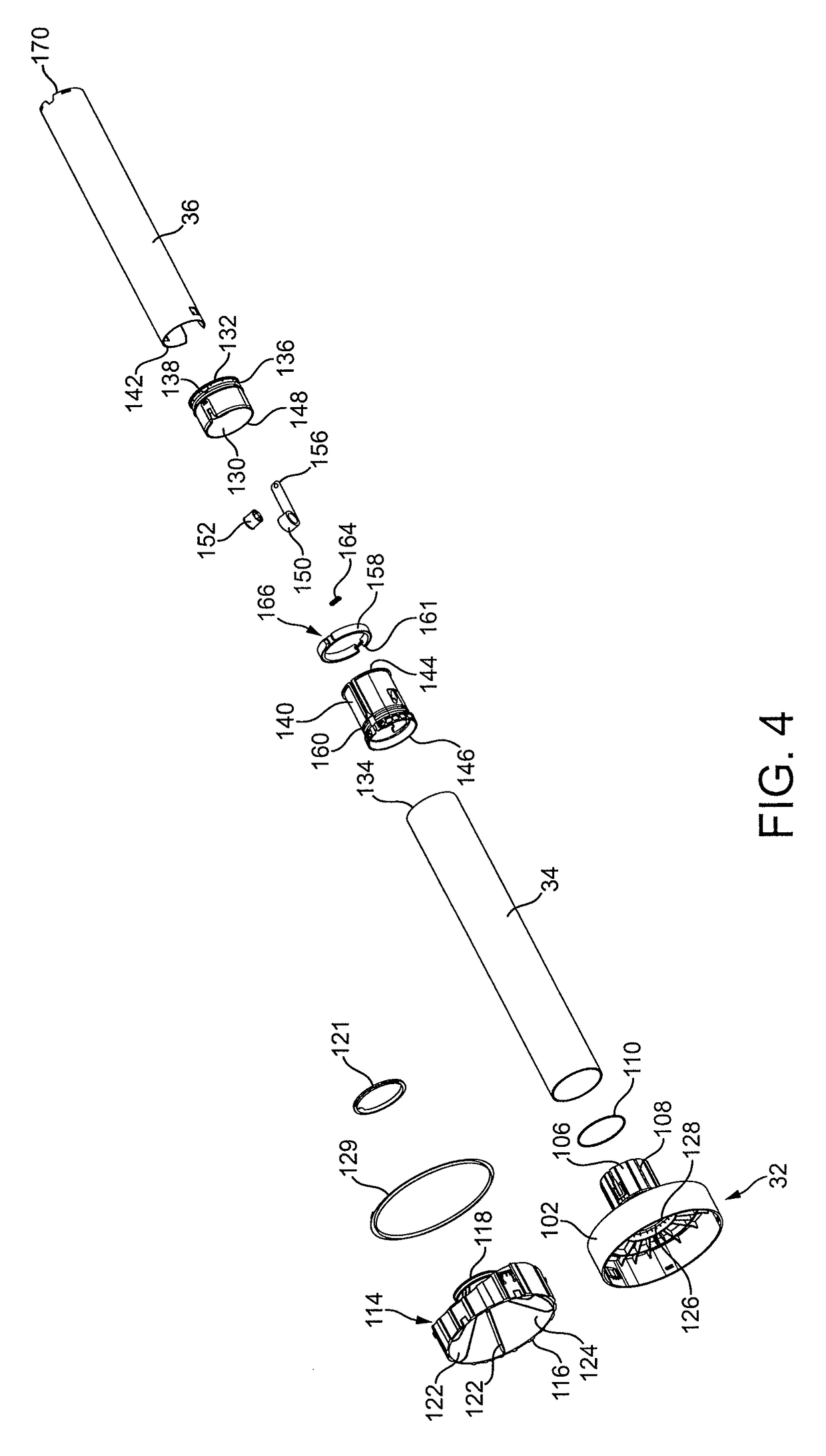
[0043]FIGS. 1 and 2 illustrate perspective views of an embodiment of a fan assembly 10. In this embodiment, the fan assembly 10 is a bladeless fan assembly, and is in the form of a domestic pedestal fan comprising a height adjustable pedestal 12 and a nozzle 14 mounted on the pedestal 12 for emitting air from the fan assembly 10. The pedestal 12 comprises a floor-standing base 16 and a height-adjustable stand in the form of a telescopic duct 18 extending upwardly from the base 16 for conveying a primary air flow from the base 16 to the nozzle 14.

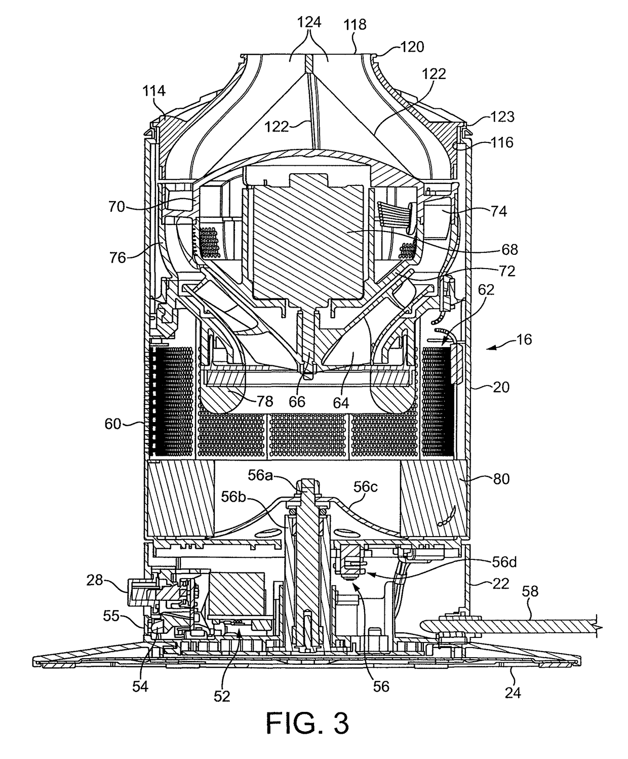
[0044]The base 16 of the pedestal 12 comprises a substantially cylindrical motor casing portion 20 mounted on a substantially cylindrical lower casing portion 22. The motor casing portion 20 and the lower casing portion 22 preferably have substantially the same external diameter so that the external surface of the motor casing portion 20 is substantially flush with the external surface of the lower casing portion 22. The lower casing portion...


PUM


Abstract

A floor standing pedestal fan for creating an air current includes a base housing an impeller and a motor for rotating the impeller to create an air flow, an air outlet, and a telescopic duct for conveying the air flow to the air outlet.

Description

REFERENCE TO RELATED APPLICATIONS[0001]This application claims the priority of United Kingdom Application Nos. 0903669.0 and 0903683.1, filed 4 Mar. 2009, the entire contents of which are incorporated herein by reference.FIELD OF THE INVENTION[0002]The present invention relates to a fan. In a preferred embodiment, the present invention relates to a pedestal fan for creating an air current in a room, office or other domestic environment.BACKGROUND OF THE INVENTION[0003]A conventional domestic fan typically includes a set of blades or vanes mounted for rotation about an axis, and drive apparatus for rotating the set of blades to generate an air flow. The movement and circulation of the air flow creates a ‘wind chill’ or breeze and, as a result, the user experiences a cooling effect as heat is dissipated through convection and evaporation.[0004]Such fans are available in a variety of sizes and shapes. For example, a ceiling fan can be at least 1 m in diameter, and is usually mounted in...

Claims


Application Information

Patent Timeline
Patent Type & Authority Patents(United States)
IPC IPC(8): F24F7/06F24F13/32
CPCF24F7/065F24F13/32F04D29/44F04D29/403F04F5/16F04D25/10F24F2221/28F04D25/08F04D29/40F04D25/06
Inventor GAMMACK, PETER DAVIDDYSON, JAMES
Owner DYSON TECH LTD
Learn More