
Combined electromagnetic wave absorber

a combined electromagnetic and absorber technology, applied in the field of electromagnetic absorbers, can solve the problems of inability to install, inhibit the arrival of electromagnetic waves at the magnetic absorber plate, and the weight and volume of conventional solid electromagnetic wave absorbers, so as to improve the effective absorption of electromagnetic waves, improve the and excellent electromagnetic wave absorption property

Inactive Publication Date: 2013-06-18
RIKEN CO LTD
View PDF8 Cites 2 Cited by
  • Summary
  • Abstract
  • Description
  • Claims
  • Application Information

AI Technical Summary

Benefits of technology

[0012]According to the present invention, a plurality of electromagnetic wave absorbent layers with a low dielectric layer interposed therebetween are disposed in a space defined by the crossed electromagnetic wave absorber on the magnetic absorber plate, thereby causing electromagnetic waves to reach the electromagnetic wave absorbent layers multiple times. Thus, a synergistic effect occurs between the attenuation effect on electromagnetic waves by thermal conversion in the respective electromagnetic wave absorbent layers and the cancelling effect of electromagnetic waves due to their phase difference. The synergistic effect can improve the effective absorption of electromagnetic waves in a wider frequency band. The aforementioned effects can be realized without increasing the content of electrically conductive material contained in the electromagnetic wave absorber. It is thus not necessary to increase the content of the electrically conductive material in order to improve the electromagnetic wave absorption property in a high-frequency band. Accordingly, the magnetic absorber plate can make full use of its electromagnetic wave absorption performance in a low-frequency band, thus providing an excellent electromagnetic wave absorption property in a wide frequency band from a low-frequency band to a high-frequency band.BEST MODES FOR CARRYING OUT THE INVENTION
[0013]Now, an electromagnetic wave absorber of the present invention will be described below in more detail with reference to the accompanying drawings.
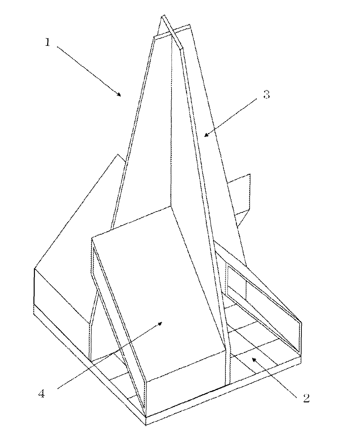
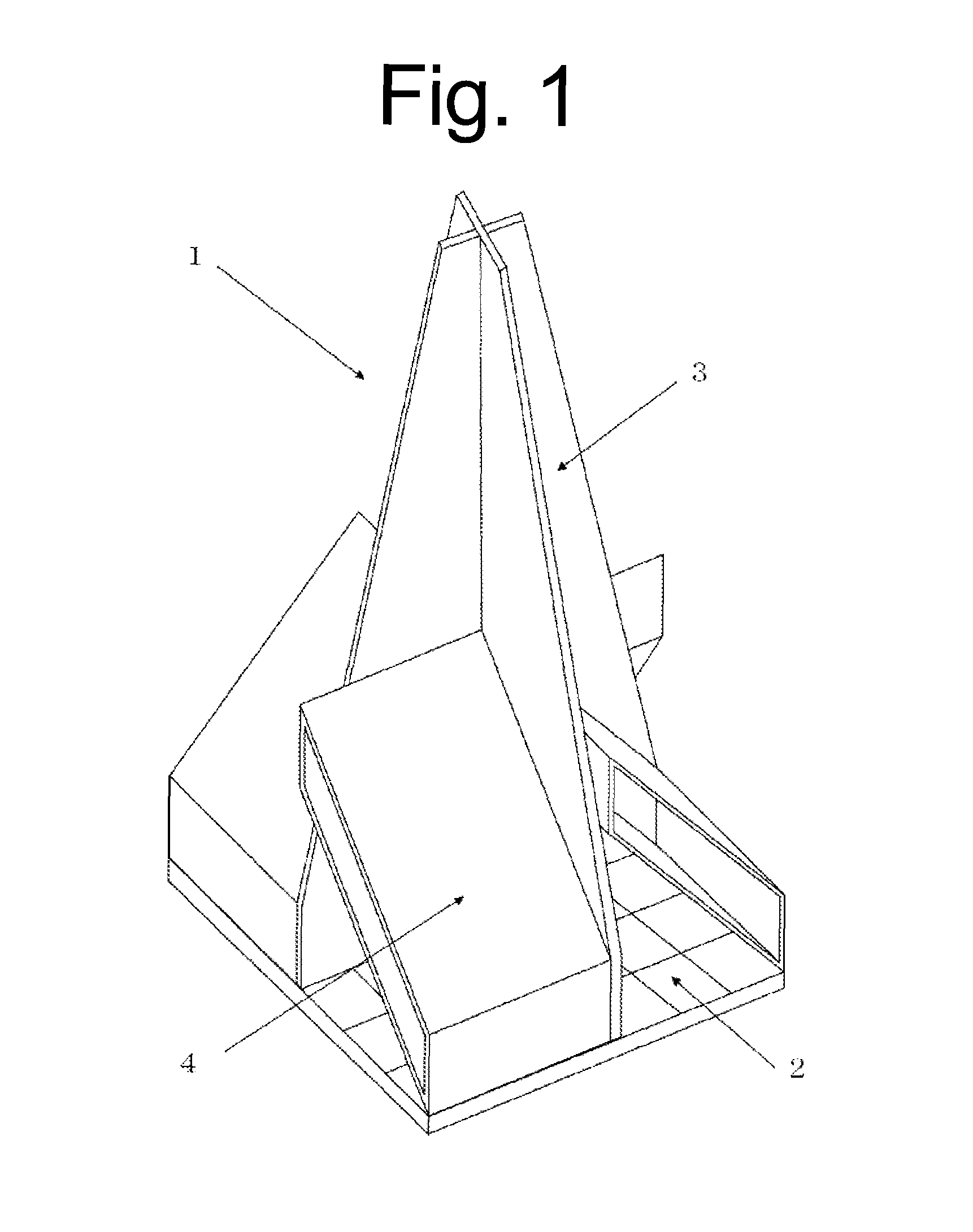
[0014]FIG. 1 illustrates an example of a combined electromagnetic wave absorber of the present invention. The combined electromagnetic wave absorber 1 of the present invention basically includes a magnetic absorber plate 2, a crossed electromagnetic wave absorber 3 disposed on the magnetic absorber plate 2, and compact electromagnetic wave absorbers 4 disposed in a space defined by the crossed electromagnetic wave absorber 3 on the magnetic absorber plate 2. In the following descriptions referring to this structure with the electromagnetic wave absorber 3 located on top of the magnetic absorber plate 2, it should be noted that the direction perpendicular to the magnetic absorber plate 2 is defined as the vertical direction or up-and-down direction, and the electromagnetic wave absorber 3 side is referred to as the upward direction. Accordingly, in the individual descriptions below, no reference will be explicitly made to directions unless otherwise specified.
[0015]The magnetic absorber plate 2 used may typically be a ferrite tile.
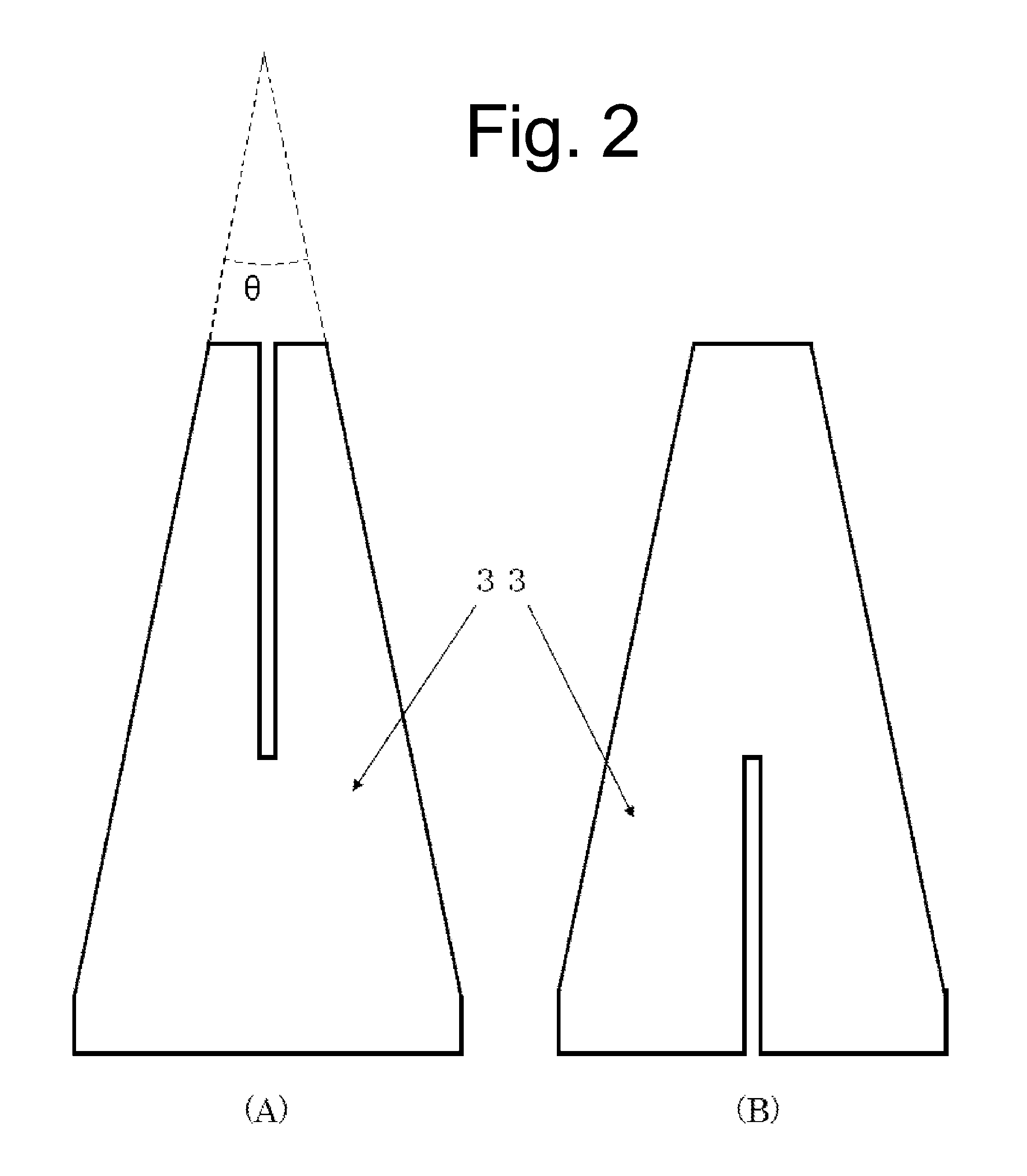
[0016]The crossed electromagnetic wave absorber 3 is formed of plates made of a dielectric loss material. The plate is typically formed, for example, in the shape of a sheet, in a corrugated cardboard structure, or in a honeycomb structure. Examples of such a dielectric loss material may include carbon-containing foamed urethane, carbon-containing foamed styrene, and carbon-containing foamed polypropylene. It is also possible to employ an alternative dielectric loss material, for example, plastics, paper, an inorganic material such as silica or alumina, or the like, which contains carbon or is coated with a carbon layer. The dielectric loss material has a carbon content of a range typically from 0.05 mass % to 1.5 mass % and preferably from 0.05 mass % to 1 mass %.
[0017]In general, the crossed electromagnetic wave absorber 3 is formed of mutually crossed polygonal dielectric loss plates of a dielectric loss material. An example of the crossed electromagnetic wave absorber 3 is shown in FIGS. 2(A) and 2(B). In this case, a polygonal dielectric loss plate 33 having a longitudinal notched portion at the top center (FIG. 2(A)) and another polygonal dielectric loss plate 33 having a longitudinal notched portion at the bottom center (FIG. 2(B)) are created, and combined together by fitting one notched portion to the other (see FIG. 3(A)). In this condition, the crossed electromagnetic wave absorber 3 is disposed perpendicular to the magnetic absorber plate 2. As used herein, the term “mutually crossed” refers to a structure in which at least part of the crossed electromagnetic wave absorber 3 has two or more dielectric loss materials mutually crossed in a cross section parallel to the magnetic absorber plate 2 on which the crossed electromagnetic wave absorber 3 is placed. The crossed electromagnetic wave absorber 3 may be fabricated in any process so long as the dielectric loss plate 33 has a mutually crossed configuration when viewed from a cross section parallel to the magnetic absorber plate 2. For example, it may be formed by affixing two bent dielectric loss plates to each other. The crossed electromagnetic wave absorber 3 is preferably directly disposed on the magnetic absorber plate 2. However, an intermediate layer can be disposed, as appropriate, between the magnetic absorber plate and the crossed electromagnetic wave absorber to such an extent that the characteristics of the magnetic absorber is not affected.

Problems solved by technology

Accordingly, conventional solid electromagnetic wave absorbers were massive both in weight and volume, posing a problem with their installability.
However, an increase in the carbon content of the compact electromagnetic wave absorber causes electromagnetic waves to be reflected on the compact electromagnetic wave absorber, thus inhibiting the arrival of the electromagnetic waves at the magnetic absorber plate.
Accordingly, the magnetic absorber plate cannot make use of its electromagnetic wave absorption performance, resulting in degradation of the property in low-frequency bands.

Method used


Image

  • Combined electromagnetic wave absorber
  • Combined electromagnetic wave absorber
  • Combined electromagnetic wave absorber

Examples


example 1

[0039]Carbon fiber of 3 mm in fiber length and 7 μm in fiber diameter was dispersed into pulp so that its carbon content was 1 mass %, and used for paper making. In this manner, an electrically conductive sheet was manufactured. This electrically conductive sheet was affixed to the front and back of an electrically nonconductive paper sheet with the paper sheet as the inner core, thereby making a corrugated cardboard sheet of a thickness of 3 mm. The sheet was then cut into pieces of 300 mm (width)×1530 mm (length). Note that the carbon content with respect to the total mass of the corrugated cardboard sheet was 0.4 mass %. The resulting corrugated cardboard sheet was dimensioned in accordance with the developed view shown in FIG. 5, so that side “a” was 600 mm, “b” was 150 mm, and “d” was 30 mm, and then bent. An adhesive was then applied to the overlap portion (d) for assembly, thereby forming a 2-layer electromagnetic wave absorber structure with a space layer (a low dielectric l...

example 2

[0040]The corrugated cardboard sheet similar to that of Example 1 was used to complete a compact electromagnetic wave absorber. Here, the compact electromagnetic wave absorber was similar to that of Example 1 except that the “b” of the developed view shown in FIG. 5 was 100 mm and the space layer (low dielectric layer) was 100 mm.

example 3

[0041]The corrugated cardboard sheet similar to that of Example 1 was used to make a plurality of hollow quadrangular pyramids based on the developed view shown in FIG. 7(A). Here, the length of the bottom side of the pyramid “e” was 150 mm and its height “f” was 500 mm. Furthermore, based on the developed view shown in FIG. 7(B), a plurality of regular square tubes were made which had a bottom side “e” of 150 mm and a height “g” of 100 mm. As shown in FIG. 7(D), the two pyramids and one regular square tube were used to make a 2-layered electromagnetic wave absorber, in which the bottom side of one pyramid and the bottom side of the other pyramid were aligned with the upper side and the lower side of the regular square tube, respectively, to form a space layer (a low dielectric layer) of 100 mm therein. The electromagnetic wave absorbers formed in this manner were disposed in the four spaces defined by the crossed electromagnetic wave absorber, four at each space, 16 in total, thus ...


PUM


Abstract

An electromagnetic wave absorber is provided which has an outstanding electromagnetic wave absorption property with a return loss of 20 dB or greater in a wide frequency band of 30 MHz to 20 GHz. A combined electromagnetic wave absorber includes a magnetic absorber plate, a crossed electromagnetic wave absorber disposed on the magnetic absorber plate, and a compact electromagnetic wave absorber disposed in a space defined by the dielectric loss plates of the crossed electromagnetic wave absorber on the magnetic absorber plate. When viewed in the direction perpendicular to the magnetic absorber plate, the compact electromagnetic wave absorber is configured in a multilayer structure having a plurality of electromagnetic wave absorbent layers with a low dielectric layer interposed therebetween.

Description

[0001]This application is a U.S. national phase filing under 35 U.S.C. §371 of PCT Application No. PCT / JP2009 / 057211, filed Apr. 8, 2009, and claims priority under 35 U.S.C. §119 to Japanese patent application no. 2008-105656, filed Apr. 15, 2008, the entireties of both of which are incorporated by reference herein.TECHNICAL FIELD[0002]The present invention relates to an electromagnetic wave absorber for absorbing electromagnetic waves, and in particular to a combined electromagnetic wave absorber used in anechoic rooms.BACKGROUND ART[0003]Anechoic rooms are widely used as a measurement chamber for evaluating electromagnetic interference (noise) generated from various types of electronics apparatuses or for evaluating EMC (Electromagnetic Compatibility) to examine for resistance of electronics apparatus against extraneous electromagnetic noise. Recently, in addition to the applications mentioned above, the anechoic room has been also employed as a calibration measurement chamber for...

Claims


Application Information

Patent Timeline
Patent Type & Authority Patents(United States)
IPC IPC(8): H01Q17/00
CPCH05K9/0003H01Q17/00H01Q17/008
Inventor HIROSE, KEITAONO, TAKASHI
Owner RIKEN CO LTD
Learn More