
Impression tray

a tray and impression technology, applied in the field of impression tray, can solve the problems of less precise, time-consuming dentist's chair, and inability to successfully incorporate replacement products produced in dental laboratories into oral cavities, so as to reduce material and labor costs, reduce the time spent in the dentist's chair, and increase the precision of implant models.

Active Publication Date: 2013-06-18
HASELHUHN KLAUS +2
View PDF15 Cites 2 Cited by
  • Summary
  • Abstract
  • Description
  • Claims
  • Application Information

AI Technical Summary

Benefits of technology

The invention proposes an impression tray that can reduce the time spent in the dentist's chair, increase the precision of an implant model and reduce material and labor expenses. The tray is designed in standard sizes, which can be used as disposable or reusable serial trays, and allows for easy removal of the impression post after curing and the finished impression is removed from the mouth. The tray is simple to handle and safe for both the dentist and patient. Additionally, the invention avoids the harmful effects of dental procedures that are involved in the production of individual impression trays, as a result of the production of silica dust. The impression tray includes struts that form a frame and a membrane located between the struts to provide flexibility in implant placements and orientation while still being stable.

Problems solved by technology

The replacement produced in a dental laboratory can only be successfully incorporated in the oral cavity without stress if the clinical situation is transferred exactly to a model.
While a precise impression is not a sufficient condition it is a necessary one for implantological-prosthetic care.
However, a drawback of this technique is that its application is error-prone and has also been proven to be less precise compared with the above-described “pick-up” technique since, inter alia, the channel-like impression of the impression post required for the three-dimensional repositioning of the position of the implant body in the impression material may only be replaced by shallow and imprecise impressions of impression elements and hence leads to unsatisfactory results for the doctor and primarily the patient.
Repositioning of the impression tray also leads to significant movements in the impression material, so the precision of the subsequent model decreases.
When using the proposed impression tray however the process of removing impression material over the screw, which process on its own is already complex but, owing to hardening of the impression material, is also limited in terms of time, may lead to considerable problems.
A further drawback is that the interplay between impression post and positioned impression tray may no longer be checked and corrected if necessary since the impression post can no longer be seen in its position relative to the impression tray.

Method used


Image

  • Impression tray
  • Impression tray
  • Impression tray

Examples


Embodiment Construction

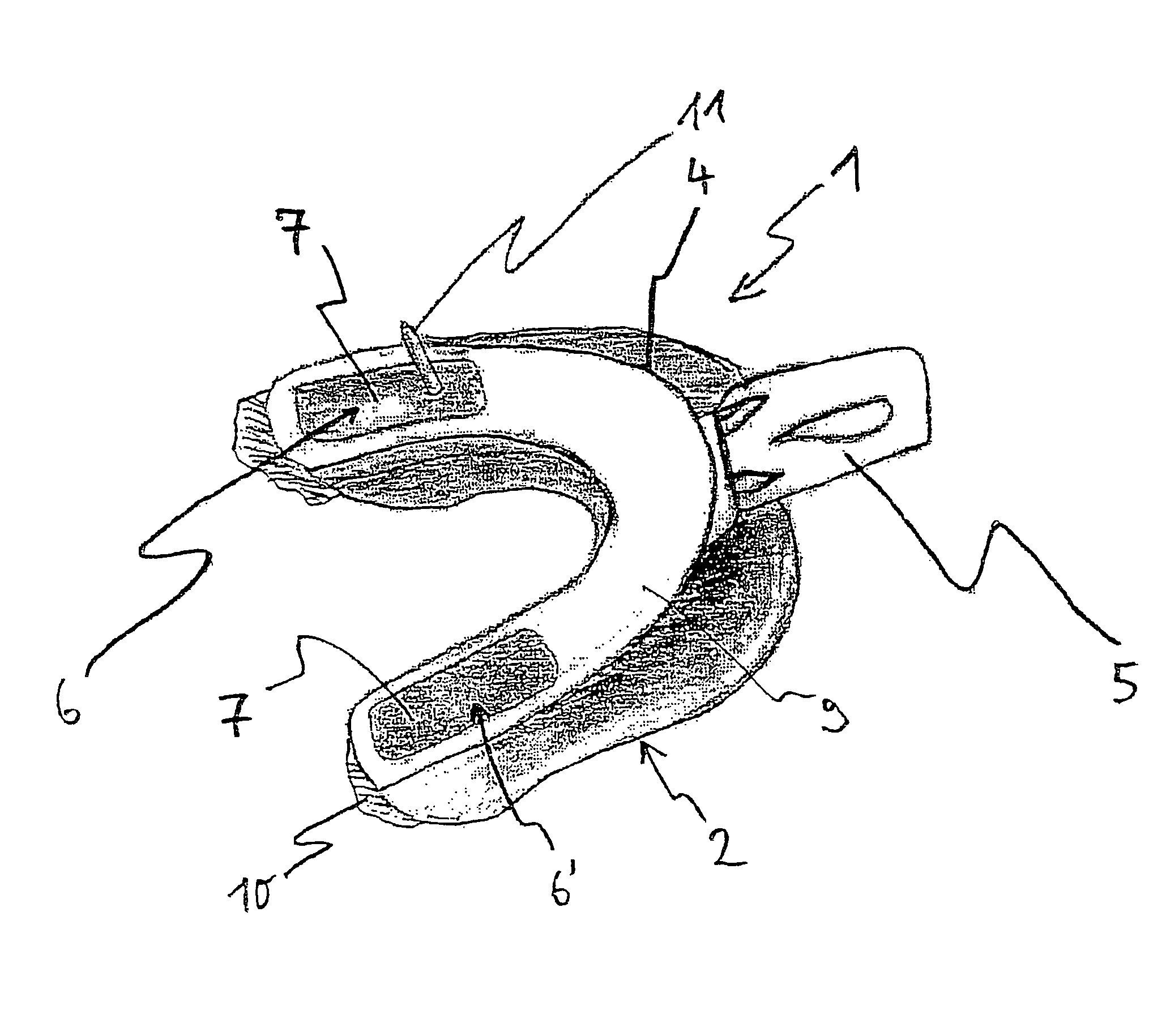
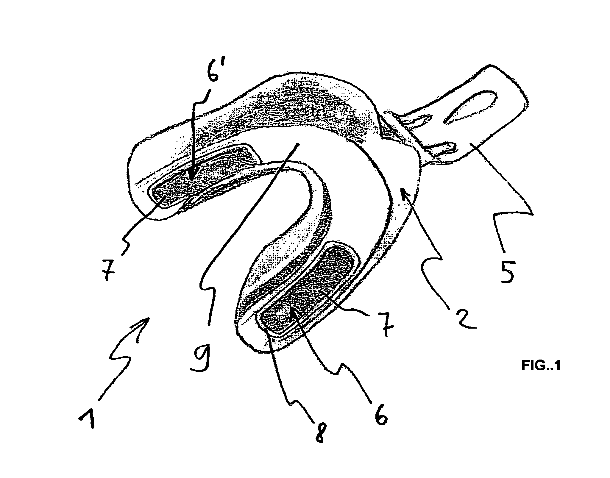
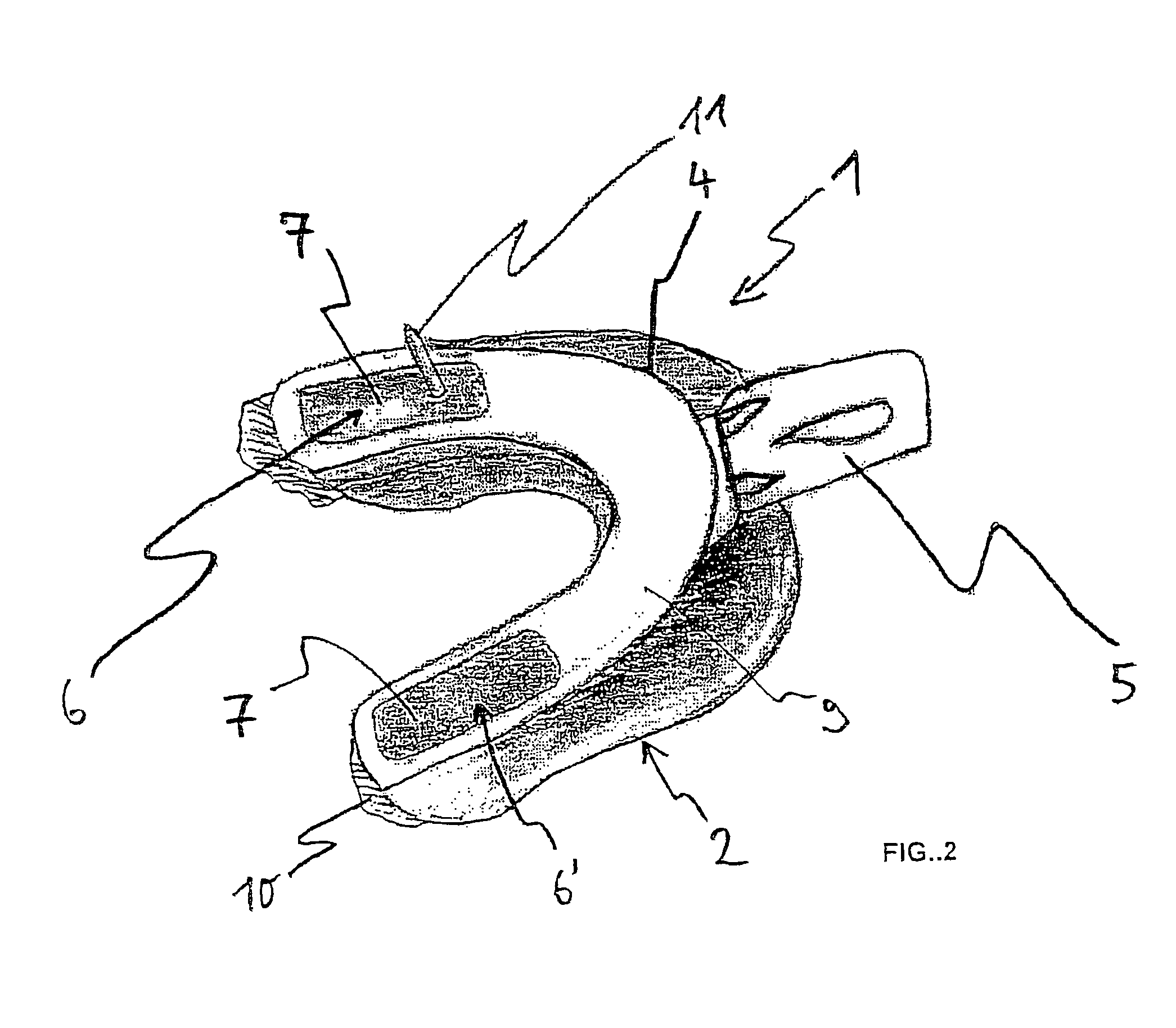
[0036]The one-piece impression tray 1 illustrated in FIG. 1 and FIG. 2 that is made of plastics material, in particular of two-component injection moulded plastics material, comprises a concave impression body 2 that is adapted to a jaw or jaw part and to the lateral edge 4 of which a tray handle 5 adjoins. At the left-hand and right-hand sides of the impression body 2 there are portions of the wall 6, 6′ with a particularly thin wall thickness constructed as a film 7 or membrane made of the same plastics material as the rest of the impression body 2. The transition from the otherwise approximately two to four millimeter thick wall 9 of the impression body 2 up to the approximately only 200 micrometer thin film 7 is formed by a transition region 8 that is approximately two millimeters wide.

[0037]FIG. 2 is intended to illustrate the use of the impression tray 1 according to the invention. The impression tray 1 is partially filled with impression material 10 and has been firmly presse...


PUM


Abstract

Disclosed is an impression tray (1) with a concave tray body (2) for taking an impression of at least one jaw part, in which at least one implant body (12) is situated, which body has a receiving aperture into which an impression post (11) may be inserted, it being possible to fill the impression tray (1) with a free-flowing hardenable impression material (10) to produce a mold for a model of the jaw part, which when used reduces the time spent in the dentist's chair, increases the precision of an implant model and finally reduces the material and labor costs in that, at least in one portion, the tray body (2) has a wall (6, 6′) which can be penetrated by an impression post (11) inserted into the implant body (12) if the impression tray (1) is placed onto the jaw part.

Description

CROSS REFERENCE TO RELATED APPLICATIONS[0001]Applicants claim priority under 35 U.S.C. §119 of European Application No. DE 10 2004 022 066.2 filed May 5, 2004. Applicants also claim priority under 35 U.S.C. §365 of PCT / EP2005 / 004794 filed May 3, 2005. The international application under PCT article 21(2) was not published in English.BACKGROUND OF THE INVENTION[0002]1. Field of the Invention[0003]The invention relates to an impression tray with a concave tray body for taking an impression of at least one jaw part, in which at least one implant body is situated, which body has a receiving aperture into which an impression post may be inserted, it being possible to fill the impression tray with a free-flowing hardenable impression material to produce a mould for a model of the jaw part.[0004]2. Description of the Related Art[0005]As is known, when one or more teeth are lost replacement roots, what are known as implants, are implanted into the jaw. These supports that are anchored in th...

Claims


Application Information

Patent Timeline
Patent Type & Authority Patents(United States)
IPC IPC(8): A61C9/00A61C8/00
CPCA61C8/0001A61C9/0006
Inventor HASELHUHN, KLAUSREIMERS, JAN-DIRKSPIEKERMANN, HUBERTUS
Owner HASELHUHN KLAUS
Learn More