
Method and system for controlling an electrical machine in a drivetrain of a motor vehicle

a technology of motor vehicles and electrical machines, applied in the direction of electric energy management, non-deflectable wheel steering, underwater vessels, etc., can solve problems such as comfort loss, and achieve the effects of effective oscillation damping, improved adaptability, and effective oscillation damping

Inactive Publication Date: 2013-06-11
ROBERT BOSCH GMBH
View PDF10 Cites 4 Cited by
  • Summary
  • Abstract
  • Description
  • Claims
  • Application Information

AI Technical Summary

Benefits of technology

[0008]The use of a torque pilot control system makes it possible to modulate the target torque for the electrical machine, said torque being predefined e.g. by a driver by way of a corresponding actuation of the accelerator pedal or by a higher-order control device, by superimposing a pilot control torque, in such a way that drivetrain oscillations are avoided or at least greatly reduced solely by way of the suitable profile over time of the corrected target torque generated in this fashion. The method and system according to the present invention have the advantage that no current state variables or operating variables from the motor vehicle are needed, along with the predefined target torque, in order to determine the pilot control torque. All that is necessary in order to define the transfer function of the pilot control unit is a physical model of the overall drivetrain, i.e. the electrical machine, wheels, a transmission, and if applicable further components of the drivetrain, which model reconstructs the oscillation capability of the mechanical structure of the overall system. This model can be defined in the context of vehicle manufacture, for example in the form of a single- or multiple-mass oscillator. From this the transfer function of the overall drivetrain, and therefrom ultimately the transfer function of the pilot control unit, can be ascertained using known mathematical methods. The pilot control unit can then be realized by way of a corresponding pilot control algorithm that is stored in a control unit, advantageously the control unit of the electrical machine.
[0018]If the drivetrain has, between the electrical machine and a shaft that is to be driven, a transmission having an adjustable conversion ratio, the system behavior then changes as a function of the current transmission conversion ratio. The exemplary embodiments and / or exemplary methods of the present invention accordingly provides that the oscillation component can be estimated with the aid of multiple stored physical models of the drivetrain; and that the respective model used for estimation is selected as a function of the current transmission conversion ratio. The model, and thus the compensation torque based thereon, can in this fashion be better adapted to the respective system behavior, and more effective oscillation damping can thereby be achieved.
[0019]Alternatively or additionally, provision can also be made that multiple parameter sets are stored for a stored physical model that is used to estimate the oscillation component, and the respective parameter set used for estimation is selected as a function of the current transmission conversion ratio. In this way as well, the model, and thus the compensation torque based thereon, can be better adapted to the respective system behavior, and more effective oscillation damping can thereby be achieved.

Problems solved by technology

The oscillations that are introduced result, however, not only in impaired comfort but in an avoidable mechanical stress on the drivetrain.

Method used


Image

  • Method and system for controlling an electrical machine in a drivetrain of a motor vehicle
  • Method and system for controlling an electrical machine in a drivetrain of a motor vehicle
  • Method and system for controlling an electrical machine in a drivetrain of a motor vehicle

Examples


Embodiment Construction

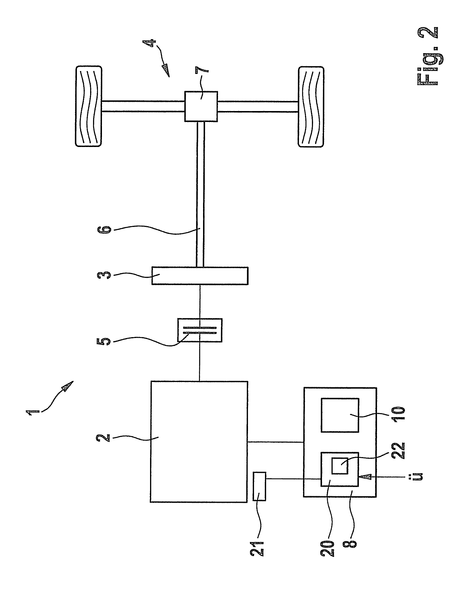
[0027]FIG. 2 schematically shows one possible embodiment of a drivetrain 1 of a motor vehicle. Drivetrain 1 for the motor vehicle (not otherwise depicted) has an electrical machine 2, a transmission 3, and a drivable axle 4 connected to the transmission output shaft. The drivable axle can be selectably a front or rear axle of the motor vehicle. Disposed between electrical machine 2 and transmission 3 is a coupling 5 that in the closed state connects electrical machine 2 to transmission 3, and in the open state decouples from electrical machine 2 a portion of drivetrain 1 located on the power output side of the internal combustion engine. Transmission 3 can be embodied as an automatic or automated transmission, or also as a manually shifted transmission. A shaft 6 to be driven (output drive shaft), proceeding from transmission 3, leads directly from the transmission output side to an input side of an axle differential 7 that converts a rotary motion of output drive shaft 6 into a rot...


PUM


Abstract

A method and a system are described for controlling an electrical machine in a drivetrain of a motor vehicle, the electrical machine being used as a drive unit for the motor vehicle. A pilot control unit determines a pilot control torque as a function of a predefined target torque of the electrical machine, the pilot control unit having a transfer function that corresponds to an oscillation component of a transfer function, ascertained in model-supported fashion for the overall drivetrain, that describes a dependence of a rotation speed of the electrical machine on a torque with which the electrical machine is operated. A control unit for the electrical machine determines a corrected target torque for the electrical machine by superimposing the pilot control torque on the predefined target torque and controlling the electrical machine as a function of the corrected target torque.

Description

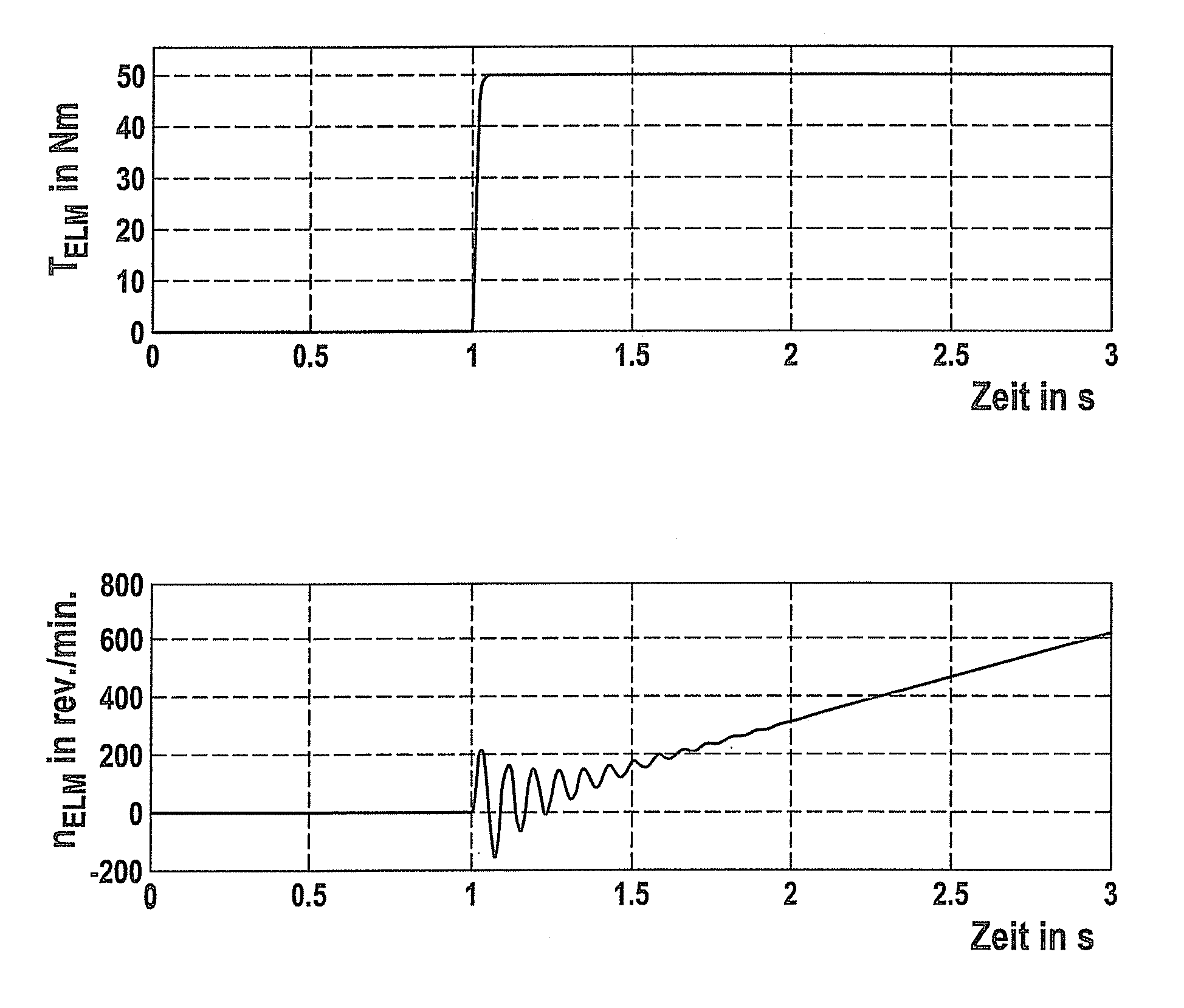
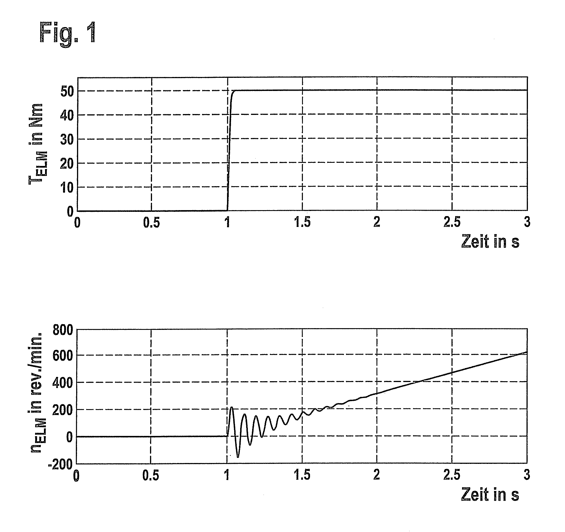
RELATED APPLICATION INFORMATION[0001]The present application claims priority to and the benefit of German patent application no. 10 2010 039 701.6, which was filed in Germany on Aug. 24, 2010, the disclosure of which is incorporated herein by reference.FIELD OF THE INVENTION[0002]The present invention relates to a method and a system for controlling an electrical machine in a drivetrain of a motor vehicle.BACKGROUND INFORMATION[0003]Electrical machines are being used more and more frequently as drive units in drivetrains of motor vehicles (electric vehicles, hybrid vehicles). A basic property of the drivetrain of a motor vehicle is its ability to oscillate. This means that especially in a context of dynamic load changes, the rotation speed of the electrical machine can oscillate considerably despite an ideally smooth profile for the propulsion torque of the electrical machine. FIG. 1 shows, by way of example, a profile over time of a torque TELM of an electrical machine, and below i...

Claims


Application Information

Patent Timeline
Patent Type & Authority Patents(United States)
IPC IPC(8): A47L1/08
CPCB60K6/48B60W30/20Y02T10/7258B60W2710/083Y02T10/6221B60W2050/0041B60L15/20Y02T10/72Y02T10/62Y02T10/64
Inventor KRETSCHMER, MARKUSGOETTING, GUNTHERKLYMENKO, MYKHAYLOPETER, MARKUS
Owner ROBERT BOSCH GMBH
Learn More