
Electrowetting display and pixel array substrate thereof and electrowetting display pixel structure thereof

a technology of electrowetting display and pixel array, which is applied in the field of electrowetting display pixel structure, can solve the problems of reducing display quality and causing delay effect, and achieve the effect of reducing delay effect of fluid medium and increasing compression ra

Inactive Publication Date: 2013-06-04
WINTEK CORP
View PDF12 Cites 5 Cited by
  • Summary
  • Abstract
  • Description
  • Claims
  • Application Information

AI Technical Summary

Benefits of technology

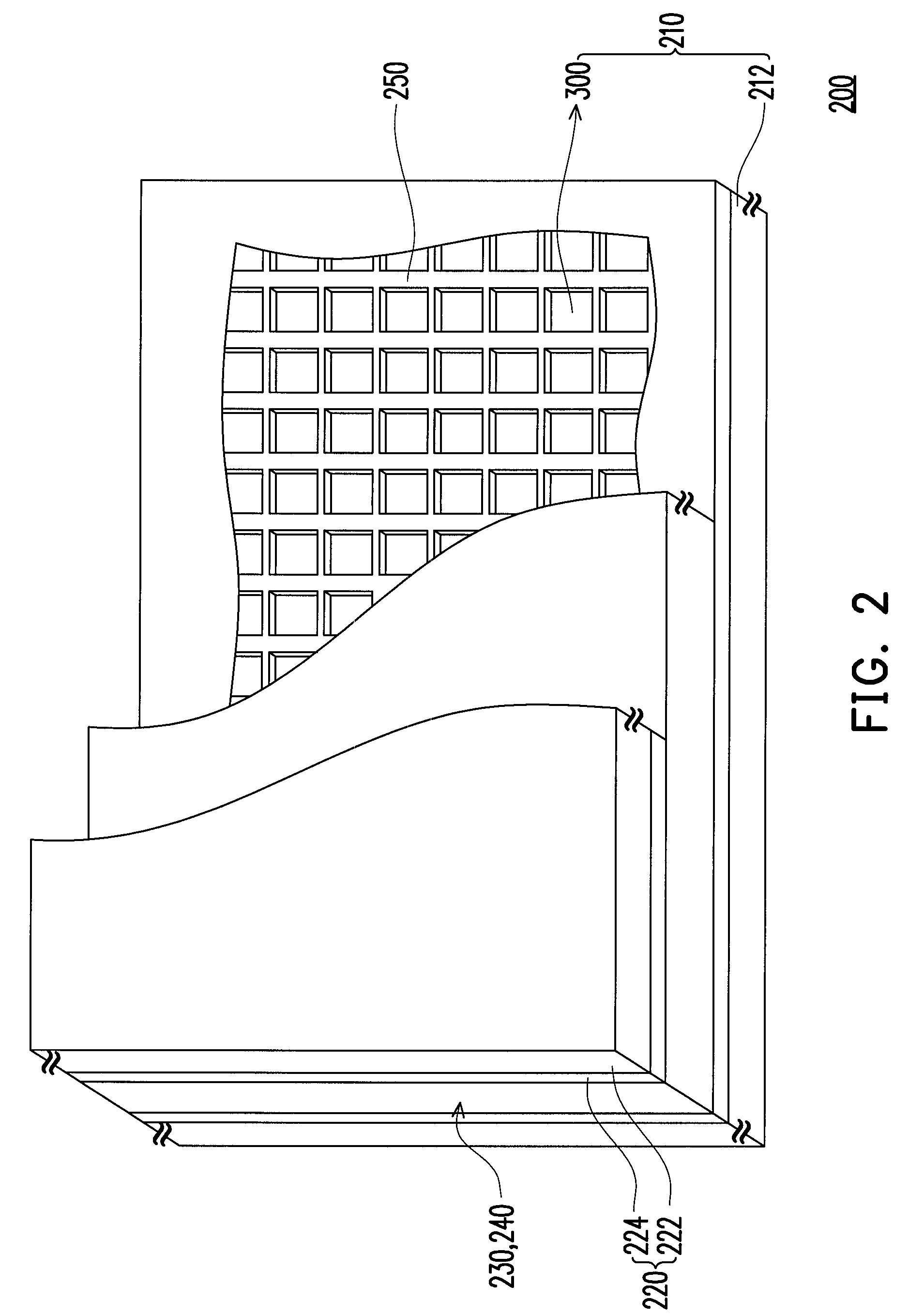
[0009]The invention is directed to a pixel array substrate and an electrowetting display pixel structure thereof. A flow guiding area disposed therein not only increases a compression rate of a fluid medium, but also reduces a delay effect of the fluid medium.
[0010]The invention is directed to an electrowetting display having the pixel array substrate and the electrowetting display pixel structure, such that the display quality thereof is greatly enhanced.
[0014]In light of the foregoing, the flow guiding areas are disposed in the pixel array substrate of the invention and the electrowetting display pixel structure thereof. By adopting the pixel array substrate and the electrowetting display pixel structure thereof in the electrowetting display, the compression rate of the fluid medium increases effectively and the delay effect of the fluid medium is reduced greatly. Overall, the electrowetting display of the invention has favorable display quality.

Problems solved by technology

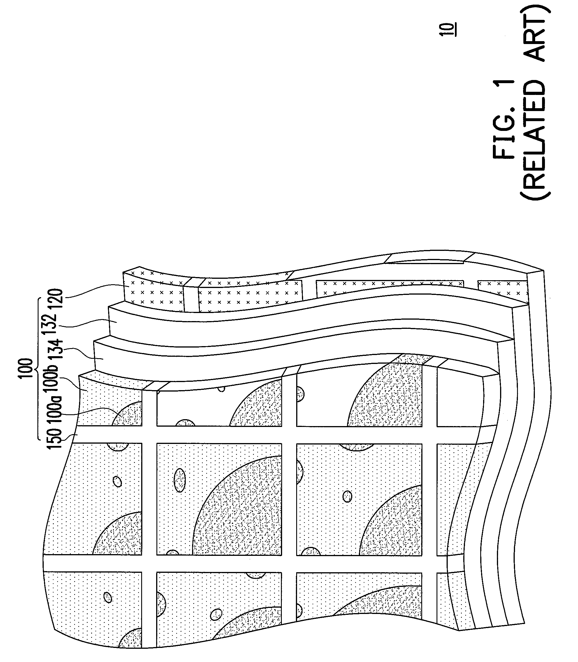
However, if the conversion rate of the two modes increases continuously, a delay effect then occurs during the compression of the oily fluid medium 100a.
Furthermore, this delay effect reduces the display quality.

Method used


Image

  • Electrowetting display and pixel array substrate thereof and electrowetting display pixel structure thereof
  • Electrowetting display and pixel array substrate thereof and electrowetting display pixel structure thereof
  • Electrowetting display and pixel array substrate thereof and electrowetting display pixel structure thereof

Examples


first embodiment

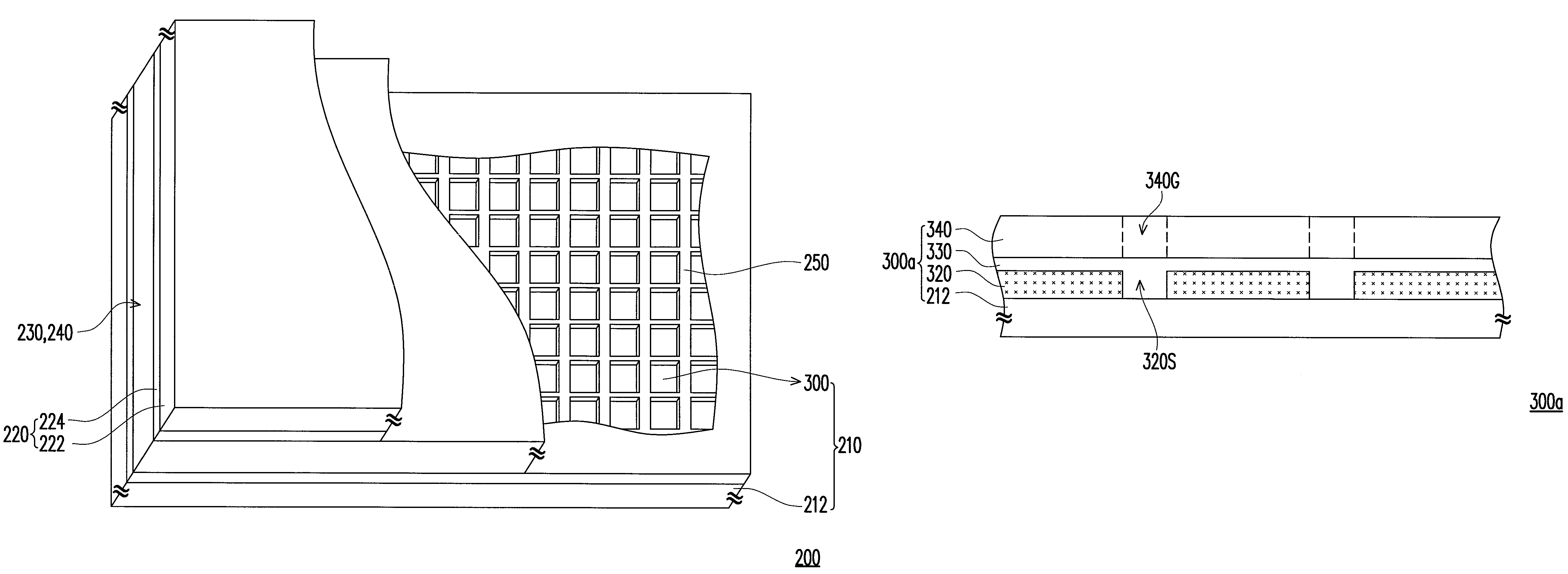
[0029]According to the flow guiding area 320G shown in FIG. 2B, an electrowetting display pixel structure 300a as depicted in FIG. 3 is further illustrated in the present embodiment. The electrowetting display pixel structure 300a of the present embodiment includes a pixel electrode 320, an insulating layer 330, and a hydrophobic layer 340. Here, the flow media 230, 240 flow on the hydrophobic layer 340. The hydrophobic layer 340 is a planarized hydrophobic layer covering the insulating layer 330 entirely, for example. In the present embodiment, hydrophobic (that is, oleophilic) materials such as a fluorinated compound, for example, Teflon (Trademark name), is adopted as a hydrophobic layer 340. Additionally, the insulating layer 330 covers the pixel electrode 320. The insulating layer 330 is configured to isolate the pixel electrode 320 and the fluid media 230, 240.

[0030]More specifically, the pixel electrode 320 of the present embodiment has at least one slit 320S. A lateral force...

second embodiment

[0033]According to the flow guiding area 320G shown in FIG. 2B, another electrowetting display pixel structure 500 as depicted in FIG. 5 is further illustrated in the present embodiment. The electrowetting display pixel structure 500 of FIG. 5 is similar to the electrowetting display pixel structure 300a of FIG. 3. The main difference between the two is that a pixel electrode 520 does not include a slit, and a plurality of flow guiding structures 550 is further disposed in the electrowetting display pixel structure 500. However, reference numbers in the present embodiment which are the same as or similar to those in the first embodiment represent the same or similar elements. Accordingly, no further description thereof is provided hereinafter.

[0034]In the present embodiment, the flow guiding structures 550 are disposed between the insulating layer 330 and a hydrophobic layer 540. The hydrophobic layer 540 covers the flow guiding structures 550 compliantly. As shown in FIG. 5, the hy...


PUM

PropertyMeasurementUnit
hydrophobicaaaaaaaaaa
insulatingaaaaaaaaaa
voltageaaaaaaaaaa

Abstract

An electrowetting display, a pixel array substrate thereof, and an electrowetting display pixel structure thereof are provided. The electrowetting display pixel structure is disposed on a substrate. The electrowetting display pixel structure includes a pixel electrode, an insulating layer and a hydrophobic layer. The pixel electrode is covered with the insulating layer, and the insulating layer is covered with the hydrophobic layer. The hydrophobic layer has at least one flow guiding area, and a flowing path of a fluid medium is determined by a layout of the flow guiding area.

Description

CROSS-REFERENCE TO RELATED APPLICATION[0001]This application claims the priority benefit of Taiwan application serial no. 98146186, filed on Dec. 31, 2009. The entirety of the above-mentioned patent application is hereby incorporated by reference herein and made a part of specification.BACKGROUND OF THE INVENTION[0002]1. Field of the Invention[0003]The invention relates to an electrowetting display technology and more particularly to an electrowetting display, a pixel array substrate thereof, and an electrowetting display pixel structure thereof.[0004]2. Description of Related Art[0005]FIG. 1 is a top view showing a conventional electrowetting display. Referring to FIG. 1, an electrowetting display 10 includes a plurality of electrowetting display pixel structures 100. Each of the electrowetting display pixel structures 100 includes a pixel electrode 120, an insulating layer 132, a hydrophobic layer 134, an oily fluid medium 100a, an aqueous fluid medium 100b, and a wall 150. The hy...

Claims


Application Information

Patent Timeline
Patent Type & Authority Patents(United States)
IPC IPC(8): G02F1/03G02B26/02G02F1/29
CPCG02B26/004
Inventor CHEN, CHENG-YIWANG, CHIH-YUAN
Owner WINTEK CORP
Learn More