Fugitive emission reducing valve arrangement

a technology of emission reduction valve and fugitive, which is applied in the direction of pipe elements, water supply installation, fluid pressure control, etc., can solve the problems of loss of sales, unappreciated true costs of industry, and huge financial burden on industry, and achieve the effect of meliorating the damage

Active Publication Date: 2013-06-04
PARKER HANNIFIN LTD HEMEL HEMPSTEAD
View PDF15 Cites 5 Cited by
  • Summary
  • Abstract
  • Description
  • Claims
  • Application Information

AI Technical Summary

Benefits of technology

[0016]The arrangement of spaced ring seals used in combination with a rotary spindle and an active compression gland produces improved performance in reducing fugitive emissions.
[0018]The seals may be positioned on different dimension diameters of the spindle; this aids in ameliorating the effect of damage with respect to performance of the valve arrangement.
[0019]Rotation of the spindle about its axis causes a valve element to reorientate between a valve open and a valve closed configuration. Beneficially, a valve arrangement is provided at an end of the spindle.

Problems solved by technology

Irrespective of the environmental impact, there is a tremendous financial burden on industry because fugitive emissions represent a huge loss of product, and cause of plant inefficiency.
However, the true costs to industry are not always appreciated, as many of the costs associated with fugitive emissions are hidden, such as labor and materials to repair leaks, wasted energy, environmental fines and clean up costs, lost sales due to a poor green image, claims for personal injury and more.

Method used


Image

  • Fugitive emission reducing valve arrangement
  • Fugitive emission reducing valve arrangement
  • Fugitive emission reducing valve arrangement

Examples


Embodiment Construction

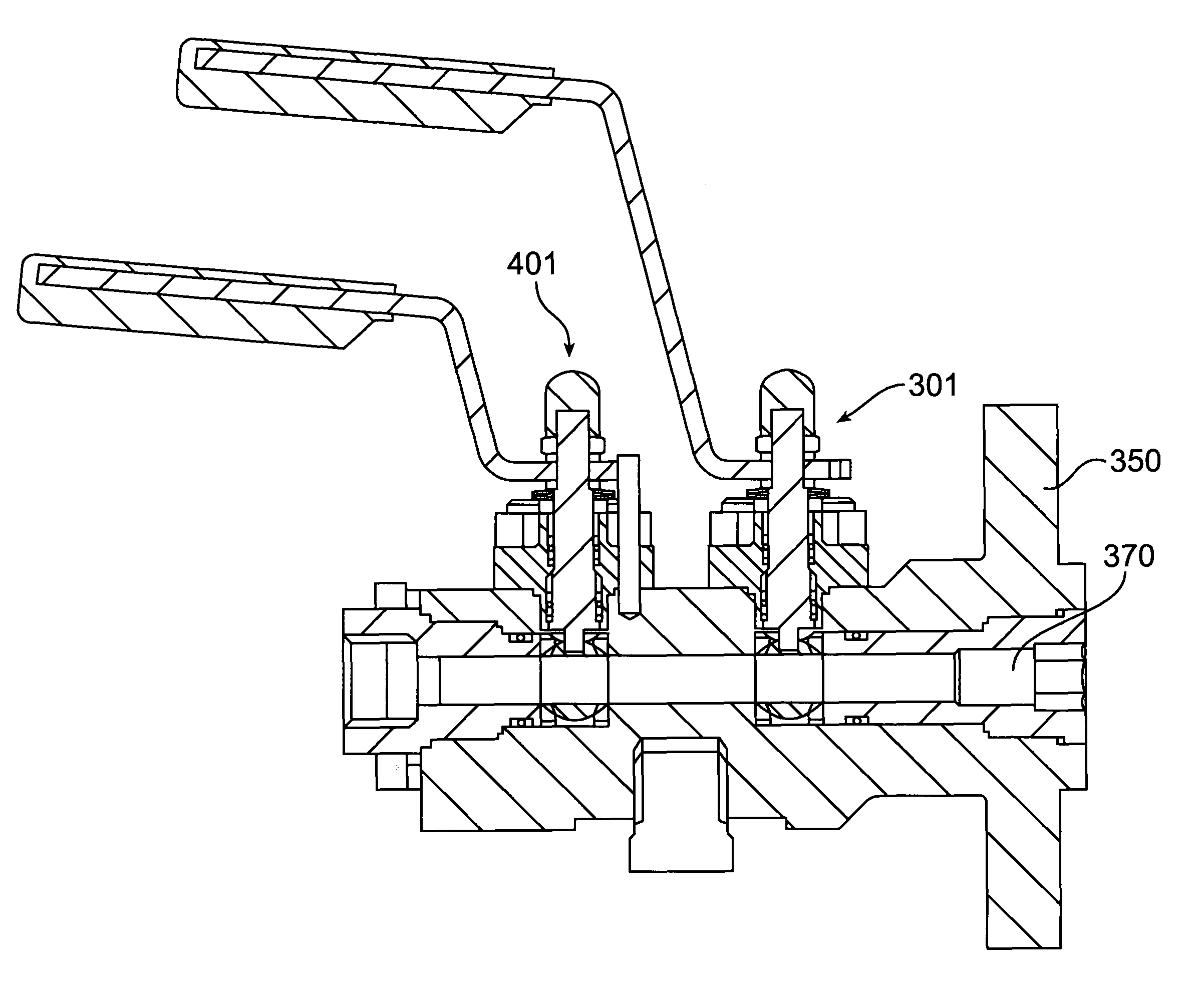
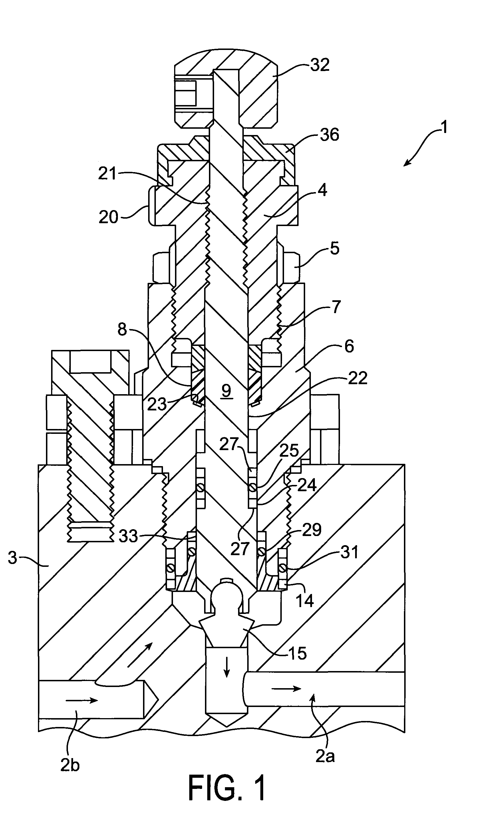
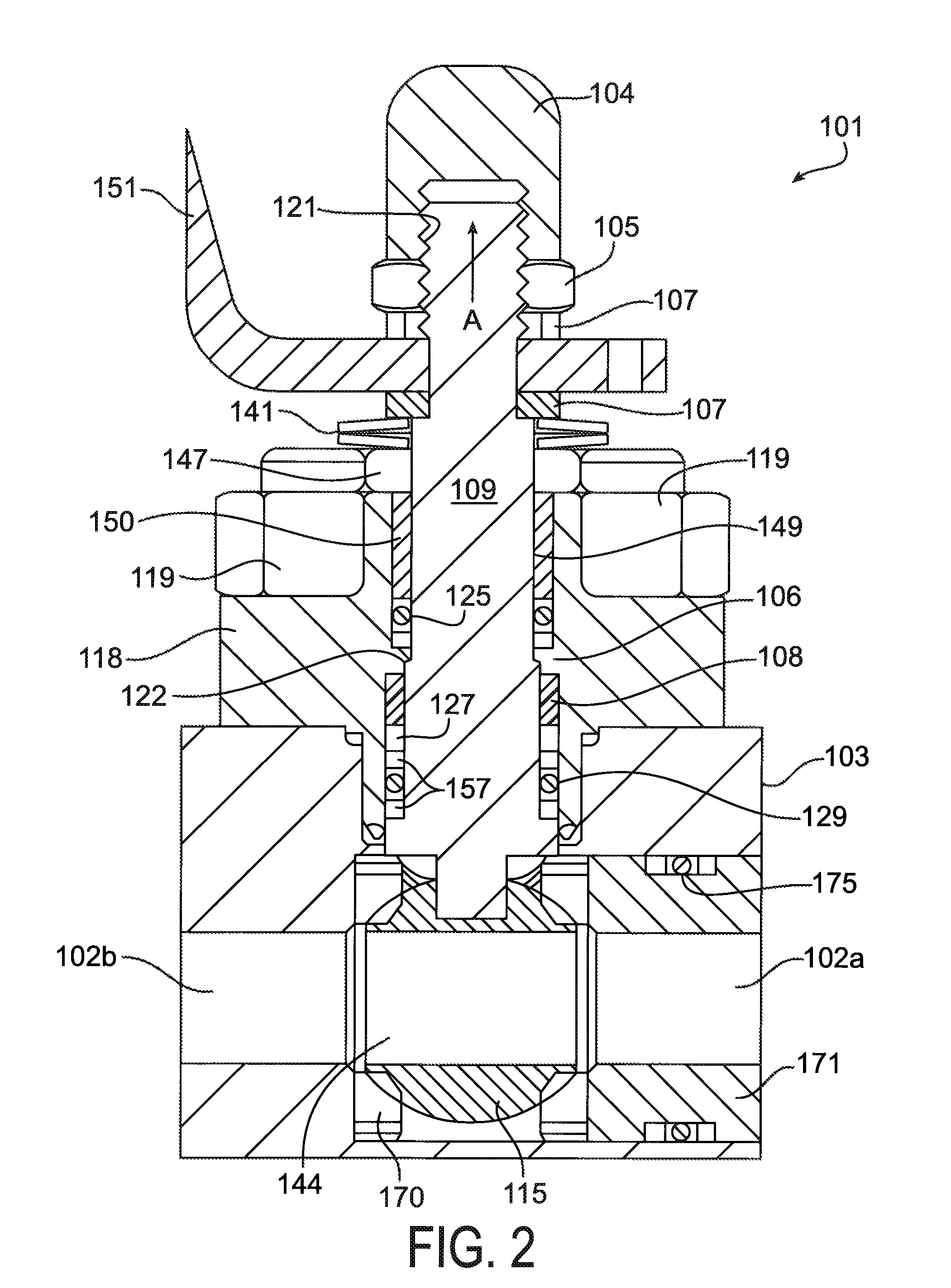
[0039]Referring to FIG. 1, there is shown a needle valve 1 for opening or closing a flowpath (having flowpath bores 2a, 2b) extending through a block 3 (such as a manifold block). Reference to needle valve should be construed broadly to cover any valve arrangement in which a valve element moves translationally with a spindle in order to open and close the valve. The needle valve includes a valve body 6 which is secured in a threaded bore in the block 3. Alternatively, or additionally, the valve body can be bolted to the block 3. The valve body 6 has an axial bore of differing diameters in order to accommodate various components of the valve.

[0040]A valve spindle 9 is positioned in the axial bore of the valve body 6, and is provided at its distal end with a manually (or machine) operable actuator 32 (such as a handle or T bar). At its proximal end the spindle carries a valve tip 15 which in use seals tight the flowpath between the bores 2a and 2b when the valve is in the closed posit...


PUM


Abstract

A valve including a valve body having a bore and a spindle received in the bore, the spindle being actuatable to open and close the valve. A compression gland seal is provided about the spindle for compression between the spindle and the bore. A first seal ring is provided about the spindle at a position spaced along the spindle from the gland seal, and provides a seal between the spindle and the bore of the valve body. A second seal ring is provided about the spindle at a position spaced along the spindle from the gland seal and the first seal ring, and provides a further seal between the spindle and the bore of the valve body.

Description

CROSS REFERENCE TO RELATED APPLICATIONS[0001]This application is a continuation of co-pending International Application No. PCT / GB2008 / 002454 filed Jul. 18, 2008, which application designated the United States, and which application claims priority to Great Britain Application No. 0714225.0, filed Jul. 20, 2007, the disclosure of each of which is incorporated herein by reference.BACKGROUND OF THE INVENTION[0002]The present invention relates to a valve arrangement. In particular, the invention relates to a valve arrangement suitable for fluid connectors or connection modules for use in connecting instrumentation equipment to a fluid container such as a process line or pressure vessel.[0003]Within the instrumentation industry, it is necessary to take fluid from a fluid container such as a process pipeline or pressure vessel, so as to take measurements of quantities such as pressure, temperature, flow and fluid level measurements.[0004]The instruments which are used to take such measur...

Claims


Application Information

Patent Timeline
Patent Type & Authority Patents(United States)
IPC IPC(8): F16K31/50
CPCF16K5/0694F16K41/04Y10T137/6069Y10T137/87917F16K41/043
Inventor SMITH, ROBERT G.DAVIS, MATHEW WILLIAMNICHOLSON, ANDREW SPENCER
Owner PARKER HANNIFIN LTD HEMEL HEMPSTEAD
Why Eureka
Try Eureka