Radio communication apparatus and relay transmission method
a technology of radio communication station and relay transmission method, which is applied in the direction of frequency-division multiplex, instruments, coding, etc., can solve the problem of increasing the distance, the attenuation of transmission distance becomes greater, etc., and achieves the effect of diversity
- Summary
- Abstract
- Description
- Claims
- Application Information
AI Technical Summary
Benefits of technology
Problems solved by technology
Method used
Image
Examples
embodiment 1
[0028](Embodiment 1)
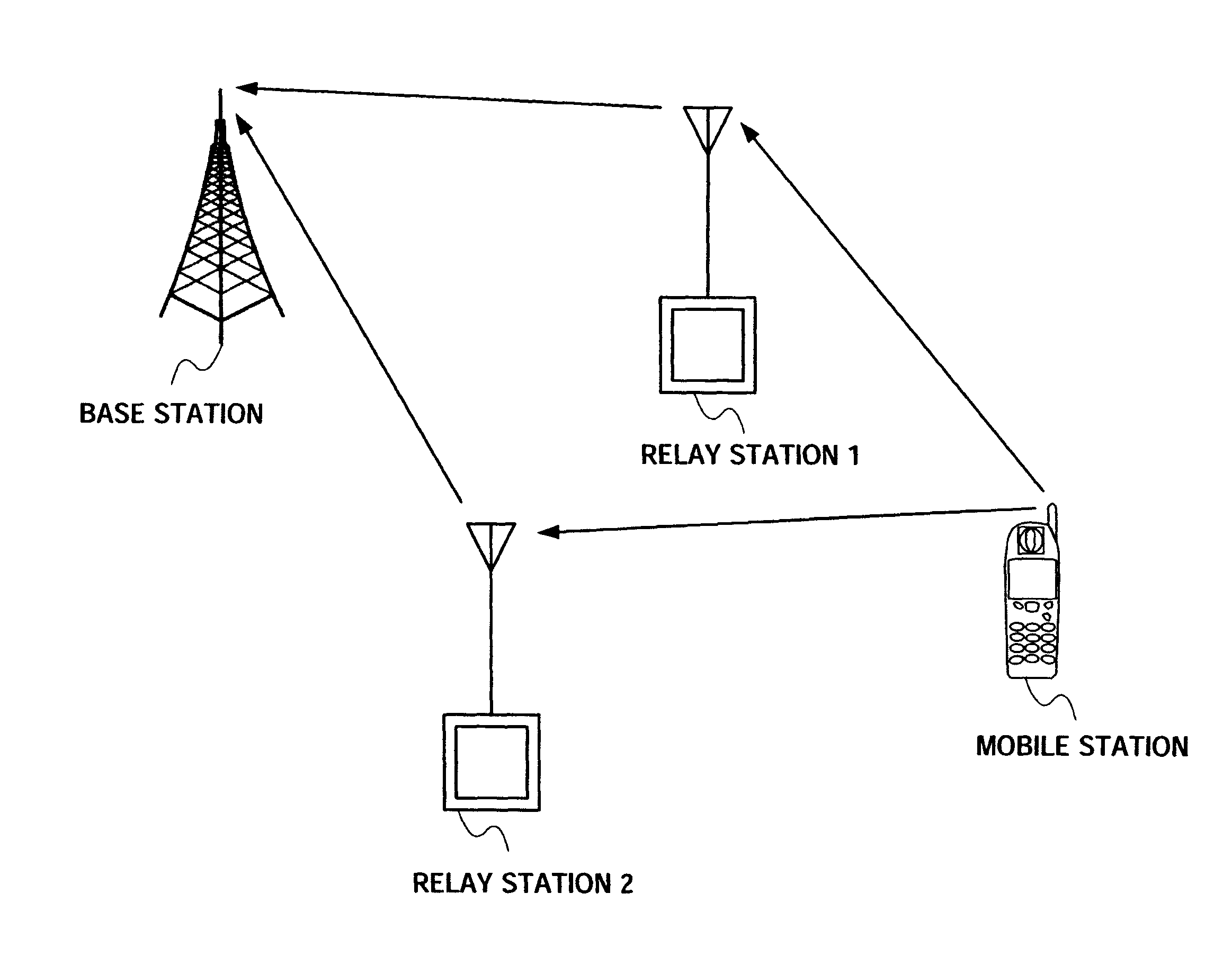
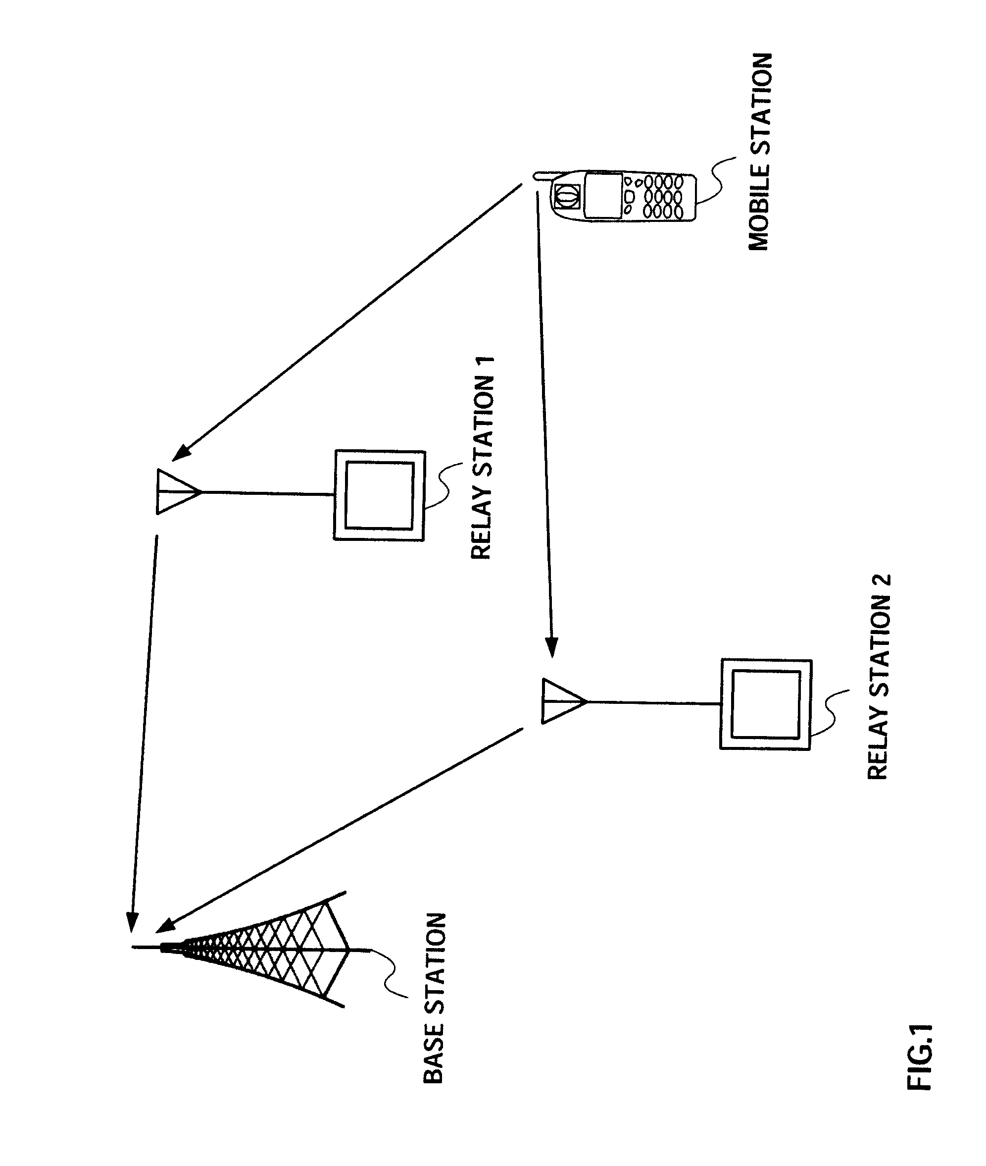
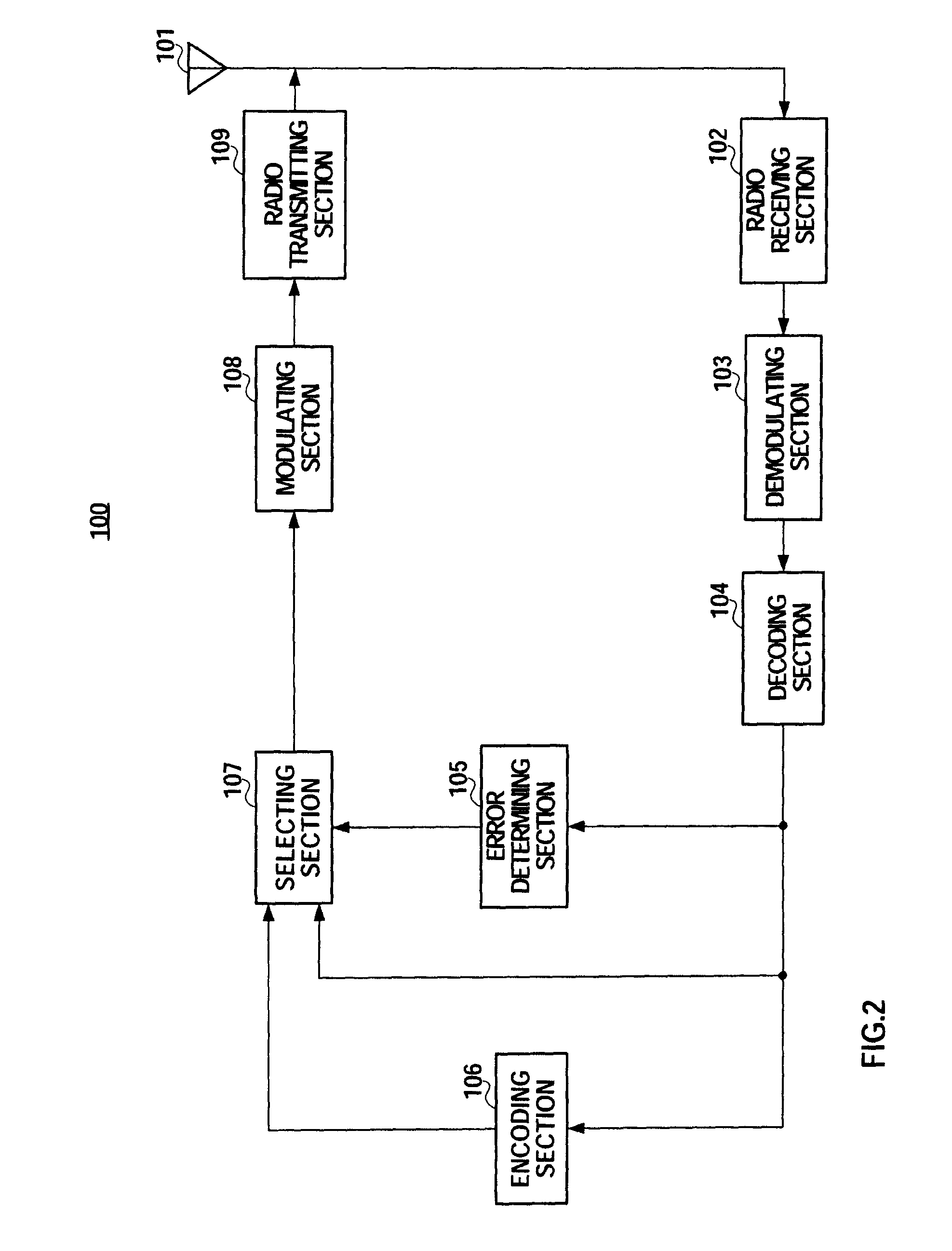
[0029]In iterative decoding such as turbo decoding, the reliability of decisions is improved and error rate performances are improved by decoding iteratively using reliability information of a decoding result (e.g. likelihood information). Accordingly, if iterative decoding is used in error correcting decoding, even when there are bits with errors in a decoding result, the number of such bits is small and the decoding result is likely to be virtually correct. That is, if iterative decoding is used in error correcting decoding, even when errors are detected in decoding result through CRC (Cyclic Redundancy Check) and so on, only part of the systematic bits with errors is included in the decoding result, and so it is likely that most of the systematic bits are correct. Accordingly, this decoding result is set in a relay transmission target even when there are errors, so that the base station can obtain diversity effect for systematic bits. Moreover, due to diversit...
embodiment 2
[0047](Embodiment 2)
[0048]Even there are errors in the decoding result (FIG. 4) in decoding section 104, the reliability of parity bits P1 to P8 included in the received data symbols (FIG. 3) may be high.
[0049]Then, when there are errors in the decoding result formed with systematic bits after error correcting decoding, the relay station of the present embodiment is the same as Embodiment 1 in transmitting data symbols including systematic bits to the base station, and is different from Embodiment 1 in including parity bits after a hard decision into the data symbols.
[0050]FIG. 7 shows the configuration of relay station 200 according to the present embodiment. In FIG. 7, the same components as Embodiment 1 (FIG. 2) will be assigned the same reference numerals and description thereof will be omitted.
[0051]Systematic bits S1 to S8 and parity bits P1 to P8 acquired in demodulating section 103 are inputted to decoding section 104 and hard decision section 201.
[0052]Hard decision section...
embodiment 3
[0059](Embodiment 3)
[0060]FIG. 9 shows the configuration of relay station 300 according to the present embodiment. In FIG. 9, the same components as Embodiment 1 (FIG. 2) will be assigned the same reference numerals and description thereof will be omitted.
[0061]The decoding result (FIG. 4) acquired in decoding section 104 is inputted to error determining section 105, encoding section 106 and repetition section 301.
[0062]Repetition section 301 repeats (i.e. duplicates) systematic bits S1′ to S8′ of the decoding result. To fix the transmission rate whether the bit sequence inputted from repetition section 301 is selected or the bit sequence (FIG. 5) inputted from encoding section 106 is selected in selecting section 107, the repetition factor (RF) here is two to match the coding rate R=½ in encoding section 106. That is, the bit sequence after repetition is as shown in FIG. 10, and the same systematic bits in twos are acquired when the RF is 2. Then repetition section 301 outputs the ...
PUM
 Abstract
Description
Claims
Application Information
 - R&D
- Intellectual Property
- Life Sciences
- Materials
- Tech Scout
- Unparalleled Data Quality
- Higher Quality Content
- 60% Fewer Hallucinations
Browse by: Latest US Patents, China's latest patents, Technical Efficacy Thesaurus, Application Domain, Technology Topic, Popular Technical Reports.
© 2025 PatSnap. All rights reserved.Legal|Privacy policy|Modern Slavery Act Transparency Statement|Sitemap|About US| Contact US: help@patsnap.com


