Pickup mechanism

a pick-up mechanism and mechanism technology, applied in the direction of transportation and packaging, thin material processing, article separation, etc., can solve the problems of not being able to the pickup mechanism cannot pick up the single piece of paper steadily, and the single piece of paper has the poor pushing force to fail to push away the blocking portion

Inactive Publication Date: 2013-05-28
FOXLINK IMAGE TECH
View PDF6 Cites 0 Cited by
  • Summary
  • Abstract
  • Description
  • Claims
  • Application Information

AI Technical Summary

Benefits of technology

[0007]As described above, when the pickup mechanism is in a status of preparing to put papers on an input tray, the power source drives the barrel element rotates upward along with the pickup shaft to make the stopping block exceed the top of supporting element. Therefore, the pickup module keeps being supported by the supporting element even if the pickup mechanism is crashed or shaken, for preventing the pickup module from swinging downward so that the papers can be effectively put under the pickup roller. Furthermore, when the pickup mechanism is in a status of picking up the papers loaded on the input tray, the barrel element is driven to rotate downward to make the stopping block of the barrel element be located under the supporting element, the pickup roller can be released freely to swing downward to pick up the papers loaded on the input tray. In this way, when a stack of papers or a single piece of paper is put on the input tray, it effectively prevents the stack of papers or the single piece of paper from needing conquer a force of the stopper element, accordingly, a drawback of prior art that the single piece of paper fails to push away the stopper element is also prevented. Therefore, it's convenient for putting the papers on the input tray so as to make the pickup mechanism pick up the papers steadily.

Problems solved by technology

However, when a single piece of paper is put on the input tray 52, the single piece of paper has the poor pushing force to fail to push away the blocking portion 72 that makes the pickup element 64 have no way of picking up the single piece of paper.
As a result, the pickup mechanism fails to pick up the papers steadily.

Method used


Image

  • Pickup mechanism
  • Pickup mechanism
  • Pickup mechanism

Examples


Embodiment Construction

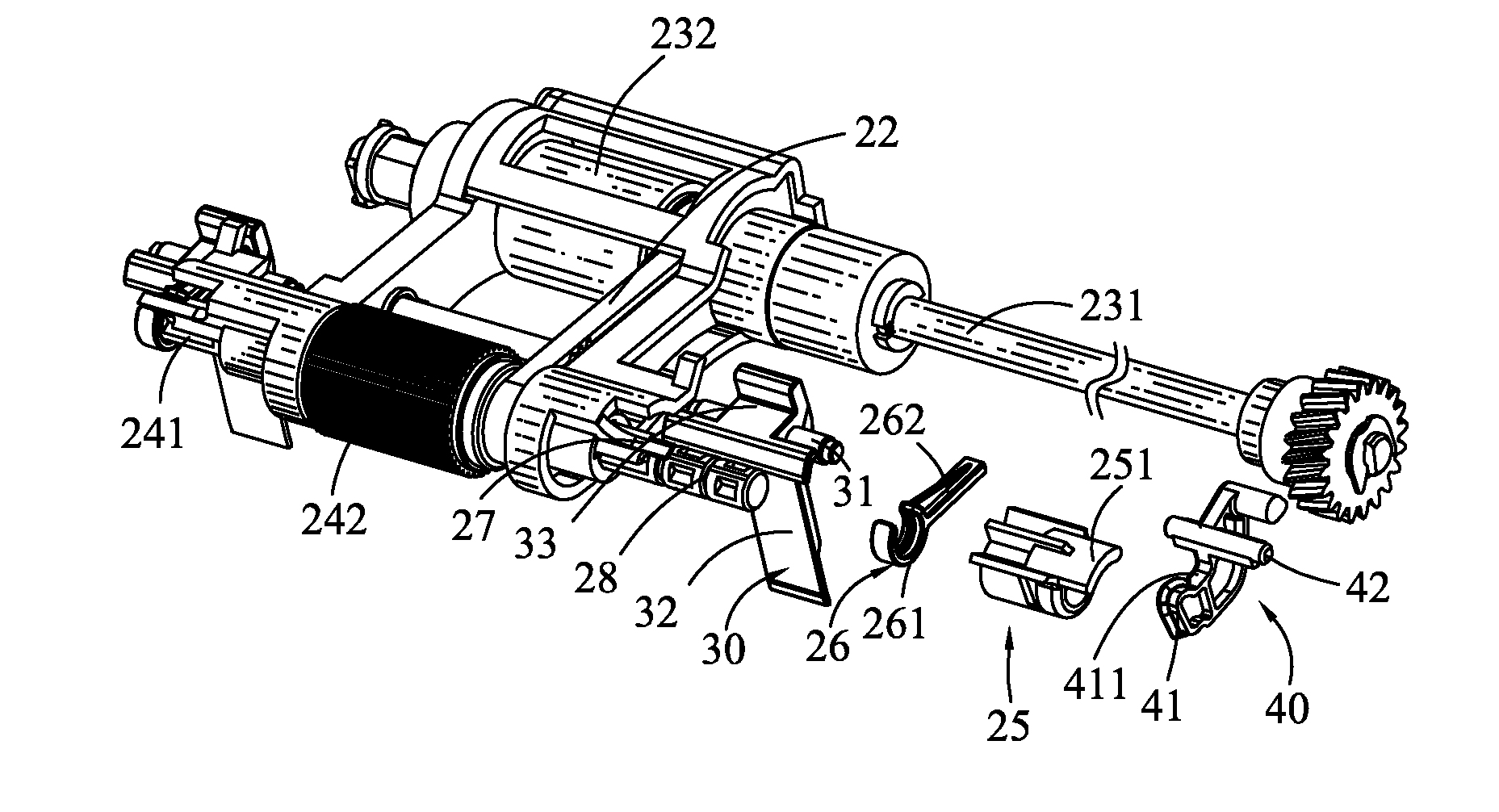
[0021]With reference to FIG. 5, FIG. 6 and FIG. 9, a pickup mechanism in accordance with the present invention is shown. The pickup mechanism includes a main frame 10, a pickup module 20, two stopper elements 30, at least a supporting element 40 and a paper detecting device (not shown).

[0022]Referring to FIG. 5, FIG. 6, FIG. 7 and FIG. 9, the main frame 10 has an upper cover 11 located at a top thereof and an input tray 12 located at a bottom thereof. The pickup module 20 positioned in the upper cover 11 of the main frame 10 includes a pickup arm 21, a transmitting element 22, a pickup element 24, a separation element 23, a barrel element 25 and a pushing element 26. The pickup element 24 is used for contacting and pulling out papers loaded on the input tray 12, and then transmitting the papers to the separation element 23. The pickup element 24 includes a pickup shaft 241 and a pickup roller 242 mounted around the pickup shaft 241. The separation element 23 can interact with a reta...


PUM


Abstract

A pickup mechanism includes a main frame, a supporting element mounted to the main frame, and a pickup module positioned in the main frame and including a pickup arm, a transmitting element, a separation element, a pickup element and a barrel element. The separation element includes a separation shaft and a separation roller. The pickup element includes a pickup shaft and a pickup roller. The separation roller and the pickup roller are restricted in the pickup arm. The transmitting element links the separation shaft and the pickup shaft. The pickup arm is pivoted at the separation shaft. The barrel element has a base portion pivotally mounted around the pickup shaft, and a stopping block. When the pickup module swings upward or downward, the barrel element is driven to rotate along with the pickup shaft to make the stopping block against the supporting element or apart from the supporting element.

Description

BACKGROUND OF THE INVENTION[0001]1. Field of the Invention[0002]The present invention generally relates to a pickup mechanism, and more particularly to a pickup mechanism capable of picking up papers steadily.[0003]2. The Related Art[0004]Referring to FIGS. 1-4, a pickup mechanism includes a main frame 50, a pickup module 60, and at least one stopper element 70. The main frame 50 has an upper cover 51 and an input tray 52. The pickup module 60 positioned in the upper cover 51 of the main frame 50 includes a pickup arm 61, a separation element 63 and a pickup element 64 of which both are restrained in the pickup arm 61. The pickup arm 61 defines a first blocking block 611 and a second blocking block 612. The stopper element 70 is set on the upper cover 51 of the main frame 50 and located between the separation element 63 and the pickup element 64. The stopper element 70 has a blocking portion 72 located at a bottom thereof and a resisting portion 74 located at a top thereof. The resi...

Claims


Application Information

Patent Timeline
Patent Type & Authority Patents(United States)
IPC IPC(8): B65H3/06
CPCB65H3/0669B65H3/0684B65H3/56B65H2403/70B65H2801/06B65H2801/39B65H3/34
Inventor WU, SHAO-YANGLEE, YUEH-SHING
Owner FOXLINK IMAGE TECH
Why Eureka
Try Eureka