
Cooled constructional element for a gas turbine

a construction element and gas turbine technology, applied in the direction of machines/engines, liquid fuel engines, mechanical equipment, etc., can solve the problems of reducing the efficiency of the machine, and remaining elements which delimit the hot gas passag

Inactive Publication Date: 2013-05-21
ANSALDO ENERGIA IP UK LTD
View PDF11 Cites 24 Cited by
  • Summary
  • Abstract
  • Description
  • Claims
  • Application Information

AI Technical Summary

Problems solved by technology

In this case, especially the components or constructional elements in the region of the combustor and also the rotor blades and stator blades of the subsequent turbine, including the remaining elements which delimit the hot gas passage, are exposed to exceptional thermal loads.
If more holes per area unit are used—with hole diameters remaining the same—the consumed amount of cooling air is also increased, which leads to a reduction of the efficiency of the machine.

Method used


Image

  • Cooled constructional element for a gas turbine
  • Cooled constructional element for a gas turbine
  • Cooled constructional element for a gas turbine

Examples


Embodiment Construction

[0014]The present invention provides a cooled constructional element for a gas turbine and a method for operating such a constructional element.

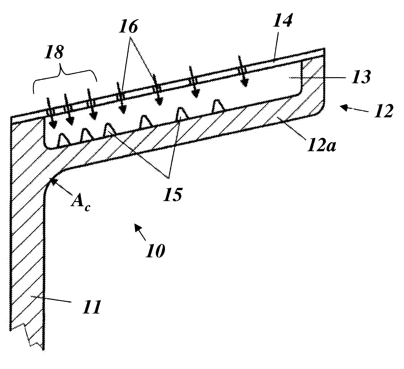
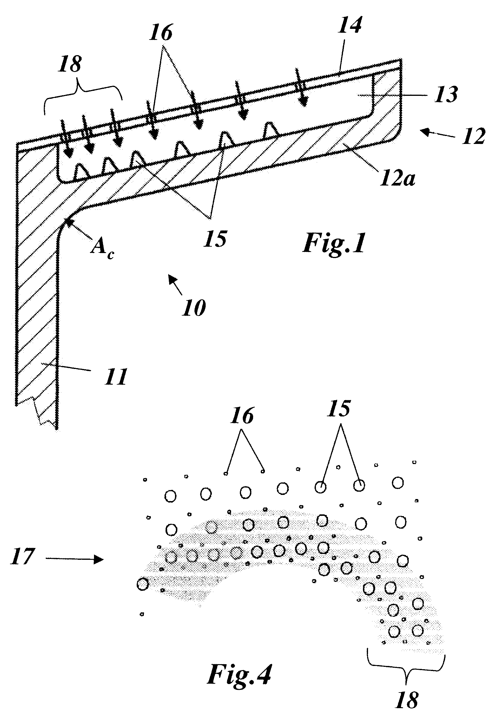
[0015]An aspect of the invention is to create a cooled constructional element of a gas turbine, especially in the case of a stator blade which is provided with a platform, the cooling of which is optimally adapted to the locally varying thermal load without creating an unnecessary increase in consumption of cooling air, i.e. minimization of the cooling air used with the same cooling intensity is achieved.

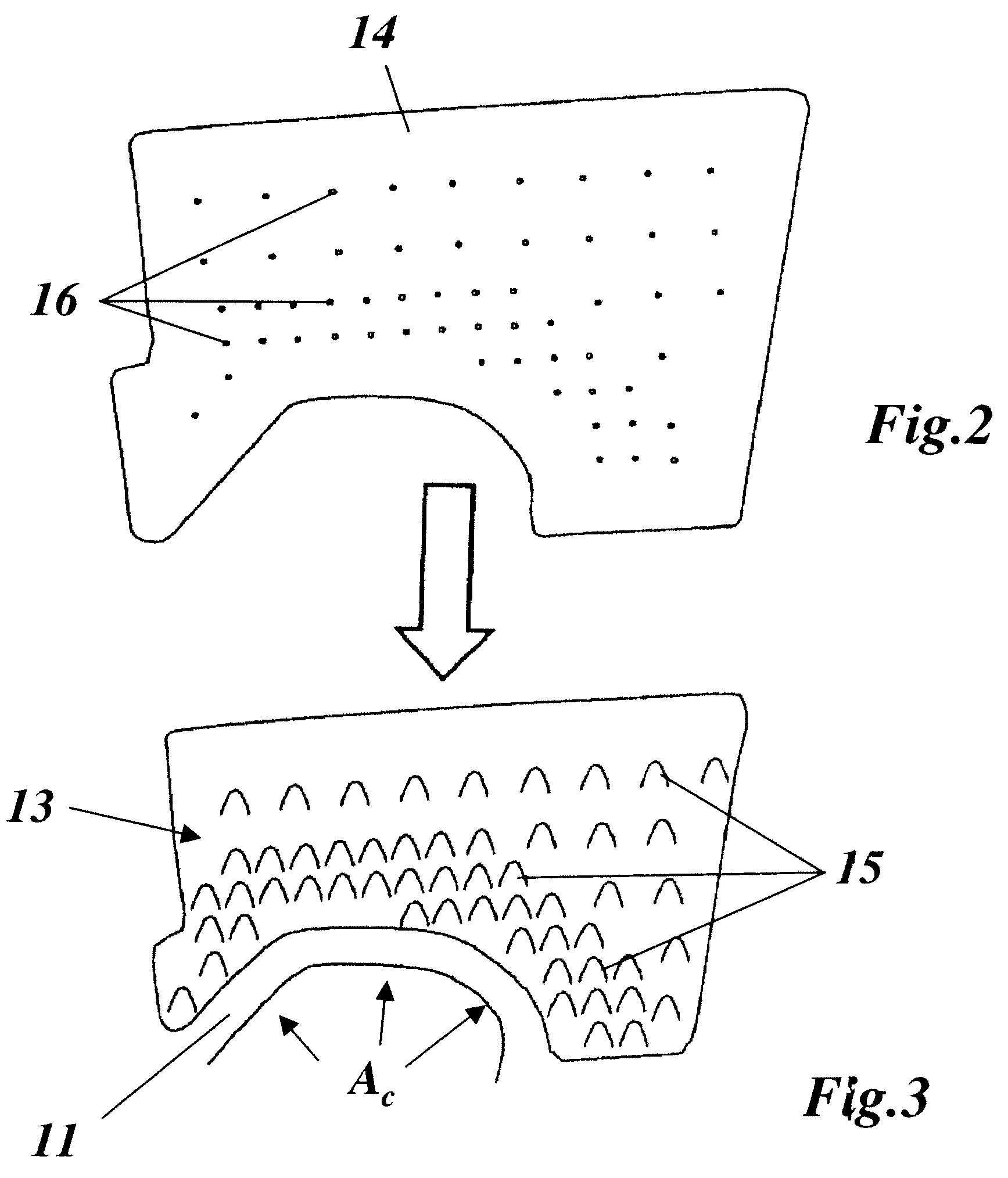
[0016]In an embodiment of the invention the thermally loaded wall which is to be cooled has a large number of pins which project from the wall on its rear side in a two-dimensional distribution, and in that the distribution of the pins has a higher density inside the thermal critical zones of the constructional element than in the remaining regions. As a result of this, the transfer of heat between wall and cooling air can be locally altered...


PUM


Abstract

A cooled constructional element for a gas turbine includes a wall having a front and a rear side. The front side is configured to be thermally loaded during operation of the turbine, and the rear side has a plurality of pins projecting therefrom in a two-dimensional distribution, the two-dimensional distribution including a higher density distribution of pins in a critical zone of the cooled constructional element than in the remaining regions of the cooled constructional element. A device is configured to create jets of a cooling medium that are directed onto the rear side of the wall in a region of the plurality of pins so as to cool the rear side of the wall by impingement.

Description

CROSS REFERENCE TO PRIOR APPLICATIONS[0001]This application is a continuation of International Patent Application No. PCT / EP2010 / 051018, filed on Jan. 28, 2010, which claims priority to Swiss Patent Application No. CH 00140 / 09 filed on Jan. 30, 2009.FIELD[0002]The present invention relates to the field of gas turbines.BACKGROUND[0003]Gas turbines are designed for ever higher operating temperatures for increasing the efficiency. In this case, especially the components or constructional elements in the region of the combustor and also the rotor blades and stator blades of the subsequent turbine, including the remaining elements which delimit the hot gas passage, are exposed to exceptional thermal loads. In order to efficiently counteract the occurring thermal loads, on the one hand especially resistant materials, such as nickel-based alloys, can be used. On the other hand, additional measures must be adopted for cooling the constructional elements, wherein different cooling methods, s...

Claims


Application Information

Patent Timeline
Patent Type & Authority Patents(United States)
IPC IPC(8): F04D31/00
CPCF01D5/187F01D25/12F05D2260/201F05D2240/81
Inventor KRUECKELS, JOERGPATHAK, MILAN
Owner ANSALDO ENERGIA IP UK LTD
Learn More